The Problem
Very often we have seen a rotator control interface for a computer. They are usually quite expensive and we convince ourselves that we do not need it. Only those who have used it, know how nice this possibility is: to write the callsign in your logging software, and “wallah” with a press a button and the rotator turns where it should!
You may also have problems with controlling your rotator: for example, you lose the degree-direction indicator from a broken gasket or from the gears inside. If there is no dealer to provide adequate spare parts and repair support, your rotator is now “blind”. Of course, you don’t need to throw it away because there is a solution!
Now, you might think that you will also need to create a program for this job… But there already is one! Anthony K3NG created it with many features and offers it to us for free. The best thing: a simple arduino nano worth €5 is more than enough!
The Solution…
In both cases above, the solution is offered by the construction of an interface – controller with Arduino. Now, you might think that you will also need to create a program for this job… But there already is one! Anthony K3NG created it with many features and offers it to us for free. The best thing: a simple arduino nano worth €5 is more than enough! It even offers possibilities that we could not have imagined (and many might not need): screen, network control, rotor control via touch screen and so much more, that could become a separate hobby altogether!
The software…
The Arduino connects to our computer via a USB cable, creates a virtual com port and through this and the application, we can program it.
So far, so good.
The “problem” is that the software from K3NG offers so much functionality that it can confuse many in setting it up. So if we download the latest version, it may need a tweak or two to work.

So if we download the latest version, it may need a tweak or two to work. Not to fear though! We are here!
You can download the version we use at SZ1A that should work out of the box so you can at least control via USB and if you add the ethernet module control through the network.
You can download it by clicking here.
You can download the version we use at SZ1A that should work out of the box so you can at least control via USB and if you add the ethernet module control through the network.
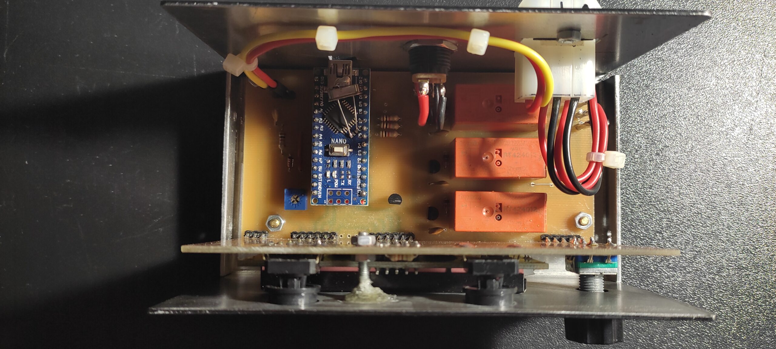
The hardware…
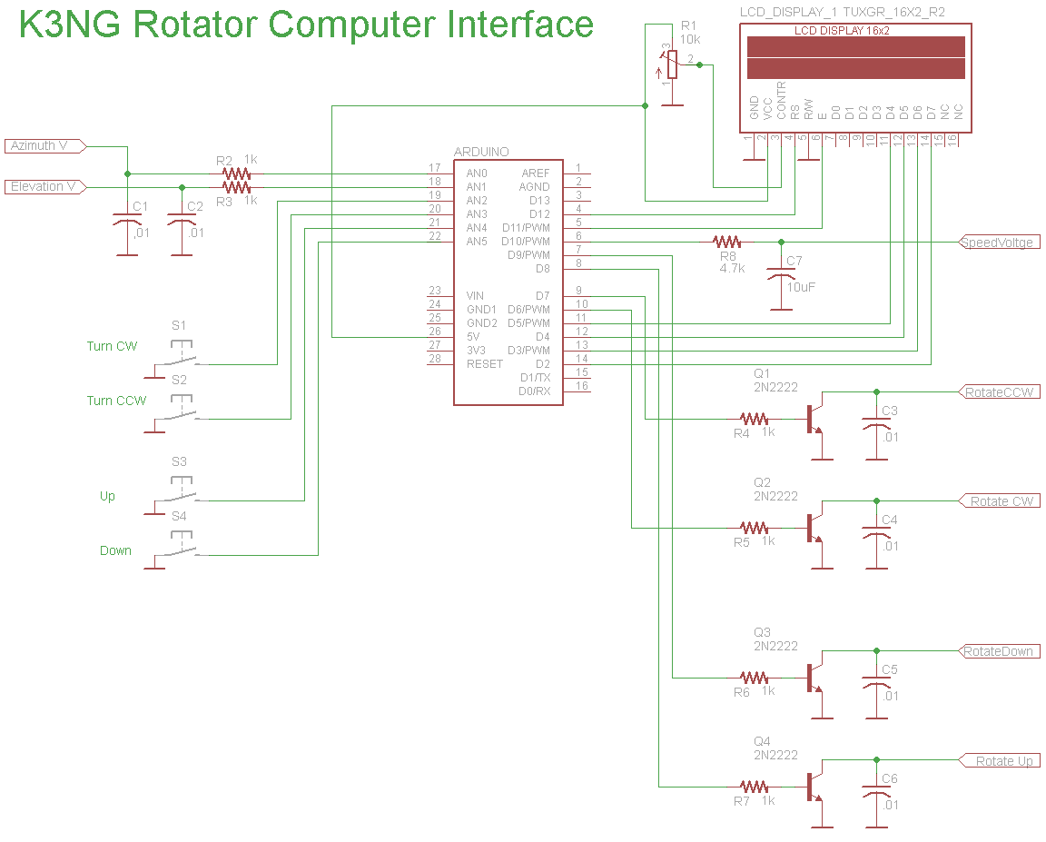
Beyond that, you still have to build something on your own too! Here is a simpler plan (just the barebones) than the K3NG default setup, since what most people want: to turn the rotator through their PC and see in real-time where the antenna is pointing.
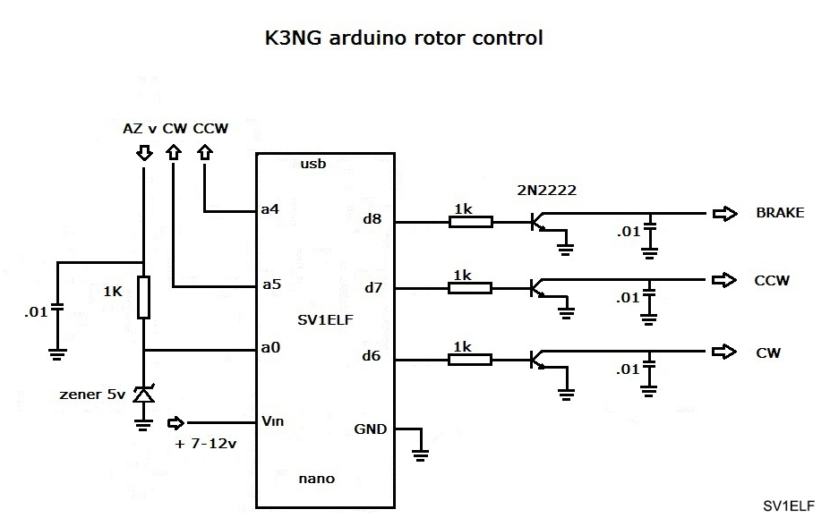
The following is a brief explanation of the pins of the circuit:
- In the analog pins A4 and A5 of the arduino, our two buttons are connected momentarily to the ground for the right or left rotation of our rotor (if we control the CW/CCW rotation with other means then we do not need to connect anything).
- In analog pin A0 we connect the indication voltage from the potentiometer of our rotator which should not exceed 5V. For this reason, we place the Zener diode (5V) for protection.
- Vin is the operating voltage of the arduino +7 to +12v max. Alternatively, we can supply it by providing 5V to the corresponding pin of the Arduino or via USB.
- GND to the ( – ) of the power supply
- In the Digital pin D6 we take the output to turn the rotator RIGHT
- In the Digital pin D7 we take the output to rotate the rotator LEFT
- In the Digital pin D8 we get the control output for the rotator BRAKE (if the rotator model has one)
The pins used in this circuit can be changed through the arduino software code, but if you download our version, they are already set as above.
We can use Arduino UNO or NANO
For some rotators or for homebrew solutions, the transistors at the outputs of cw, ccw, brake are not enough, but we must connect relays to control the movement. YAESU DXA, DXC, SDX series have control output and do not require relays. Others such as a other models from YAESU or the Hygain HAM IV rotator or even a homebrew rotator will most likely require relays after each transistor.
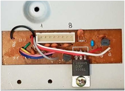
Yaesu SDX
In the following photo we see the connector inside a ΥAESU SDX rotator controller and we explain how and where we will connect our control circuit.
The connection between the circuit and the rotator is as follows:
- Pin #1: Rotate Right (CW ) – d6
- Pin #2: Rotate Left (CCW) – d7
- Pin #3: Speed control – (here we have to provide up to +5v via a trimmer for the desired rotor speed if we want to control it)
- Pin #4: Rotator position indicator –a0
- Pin #5: Ground – GND
- Pin #6: Voltage – maximum calibration voltage output of the rotator
- Pin #7: Ground – GND
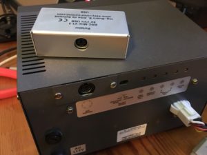
Yaesu DXA, DXC
On some models the connectors ends at the back of the rotor (Mini-Din connector, DXA, DXC model). So we do not need to open it up at all.
The connection here is made as follows:
Mini-Din connector
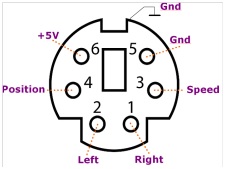
- Pin 1 Rotate Right (CW ) – d6
- Pin 2 Rotate Left (CCW) – d7
- Pin 3 Speed control – (here we have to provide up to +5v via a trimmer for the desired rotor speed if we want to control it)
- Pin 4 Rotator position indicator –a0
- Pin 5 Ground – GND
- Pin 6 voltage output for calibration
And the others…
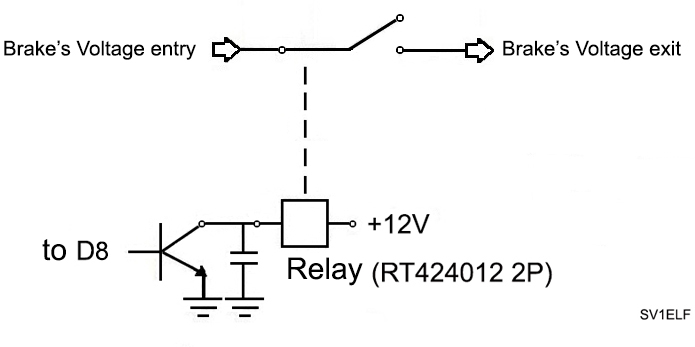
The following diagram with two relays, two contacts each, is used in the case of a simple rotator that has no external control output.
- On the left side is connected the voltage from the transformer, rectifier (this is the DC constant voltage) that the controller has to supply the rotator.
- On the right side of the circuit is the voltage output to the rotator (at the connector on the back of the controller).
It functions as follows:
The DC voltage from the controller goes to the two middle contacts of the relays. When output D6 is activated, ie we want to turn our rotor to the right (CW), the corresponding relay is activated and this voltage goes to the rotator. When output D7 (CCW drive) is activated the voltage goes back to the rotor but this time is inverted.

Additionally, when our rotor has a brake then we also use another relay to control the voltage of the brake
More information about your rotator control circuit via a PC can be found on K3NG’s website
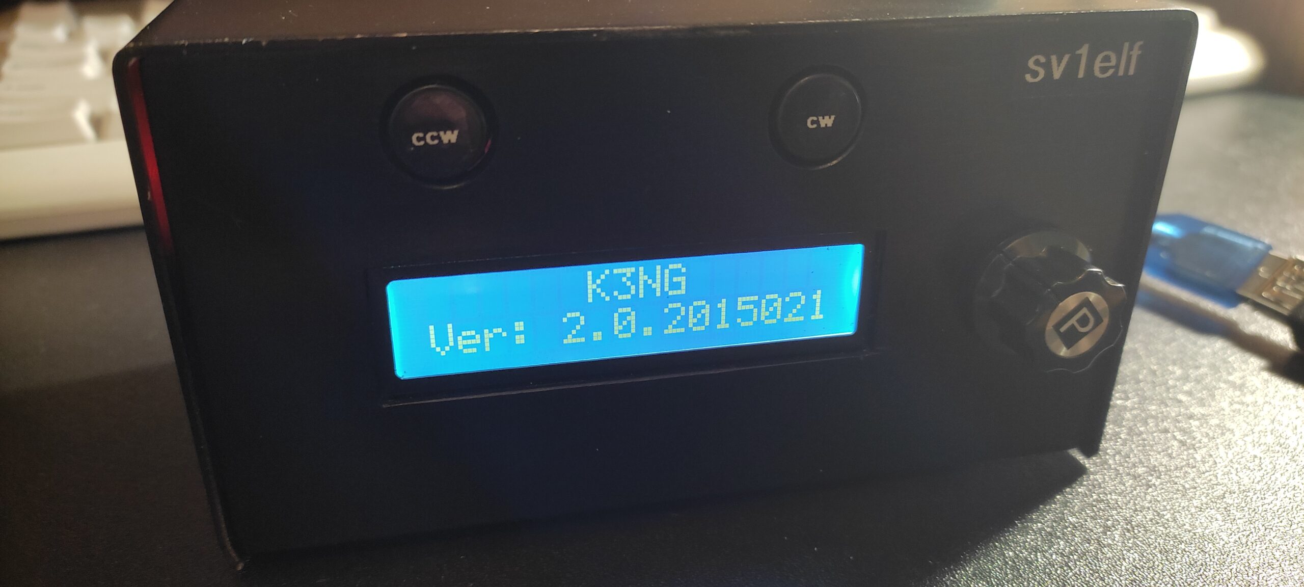
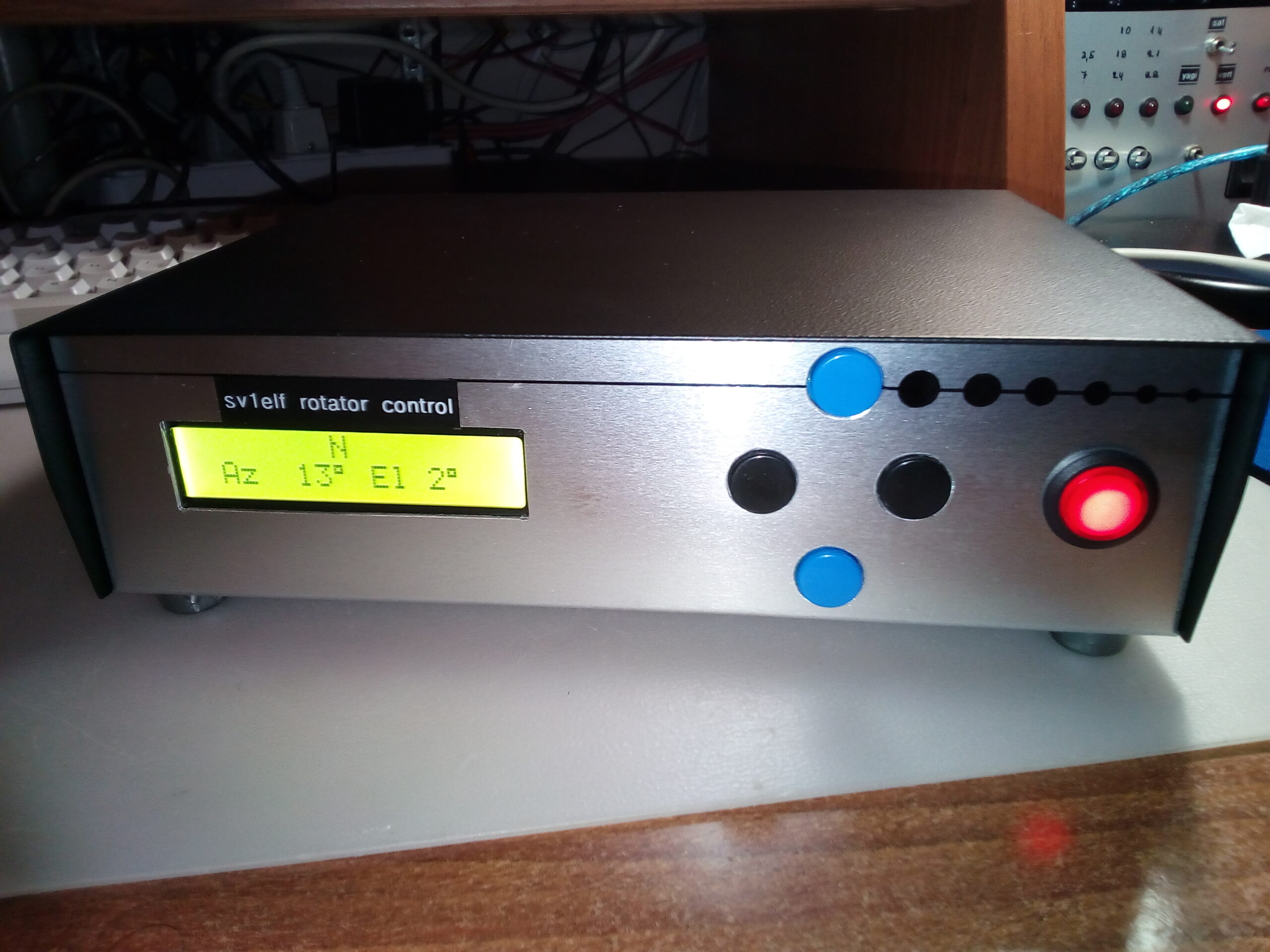
Standalone controller
The possibilities of control do not stop here. We can build a standalone controller such as one that has a screen and preset buttons but also with many more extras such as electronic compasses and GPS for indication accuracy for example for EME use, as well as various types of screens…
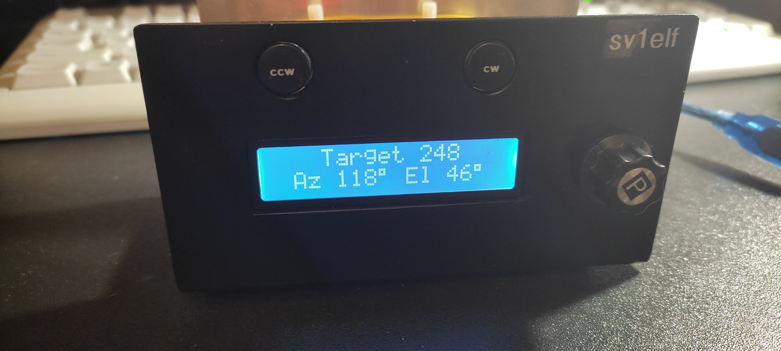
Elevation & Azimuth Version
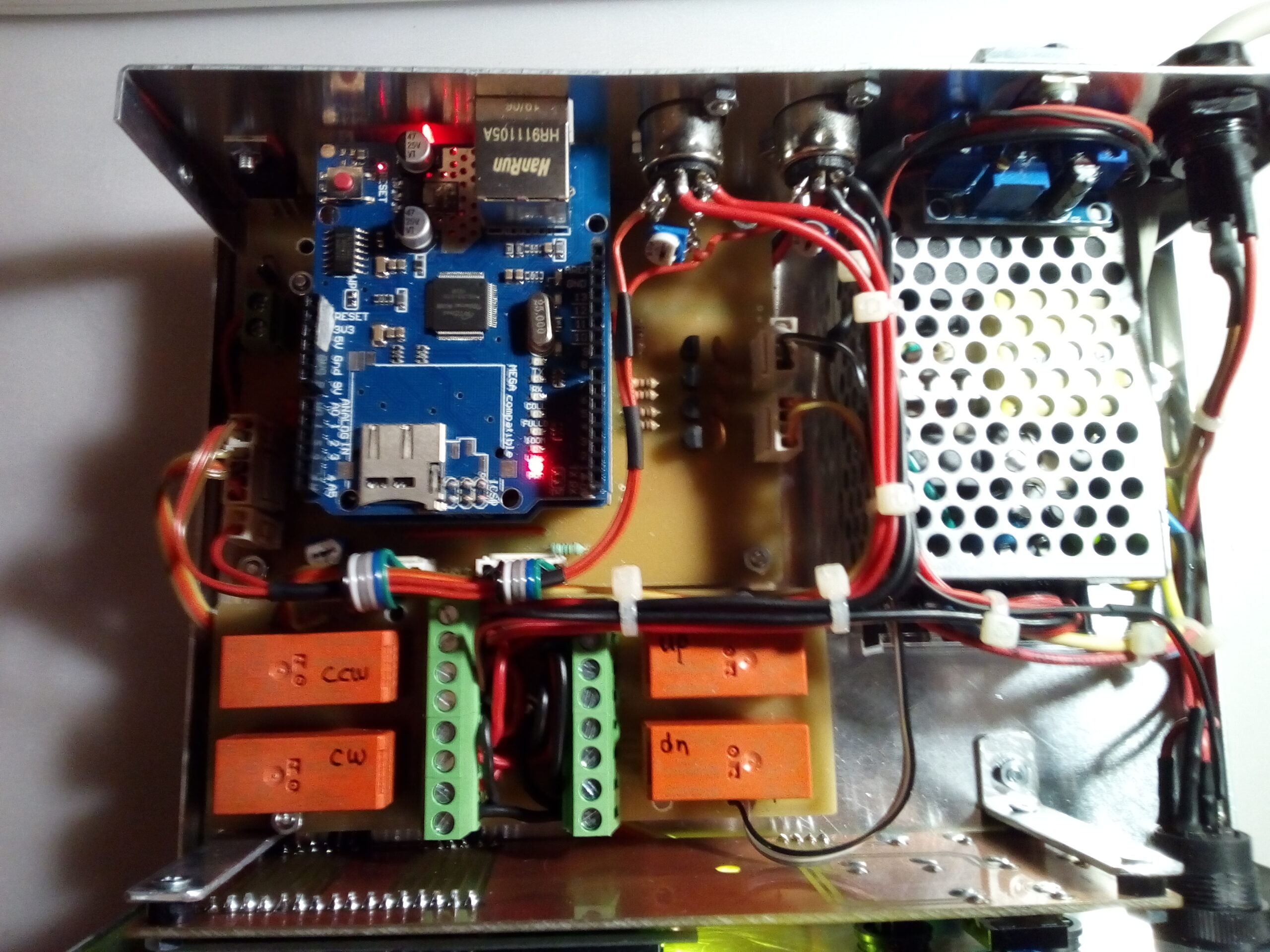
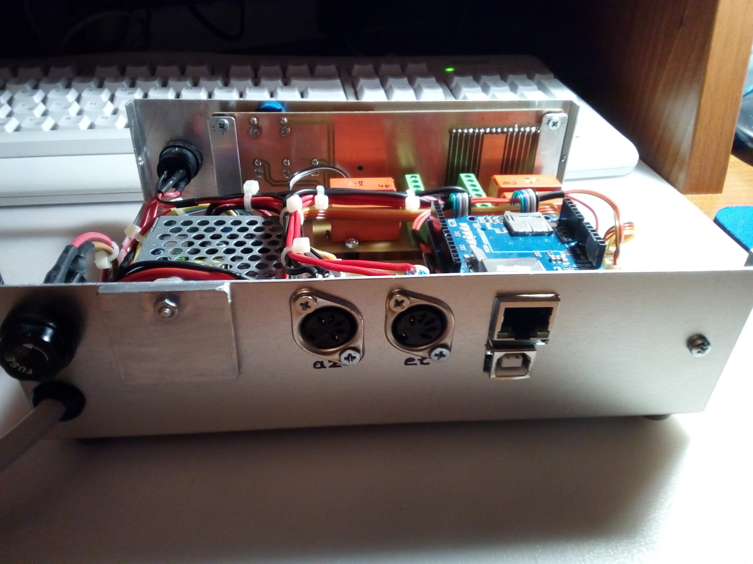
Of course in this case we have added a screen (supported by software) and a power supply that corresponds to the needs of our rotator. The logic, however, remains the same….
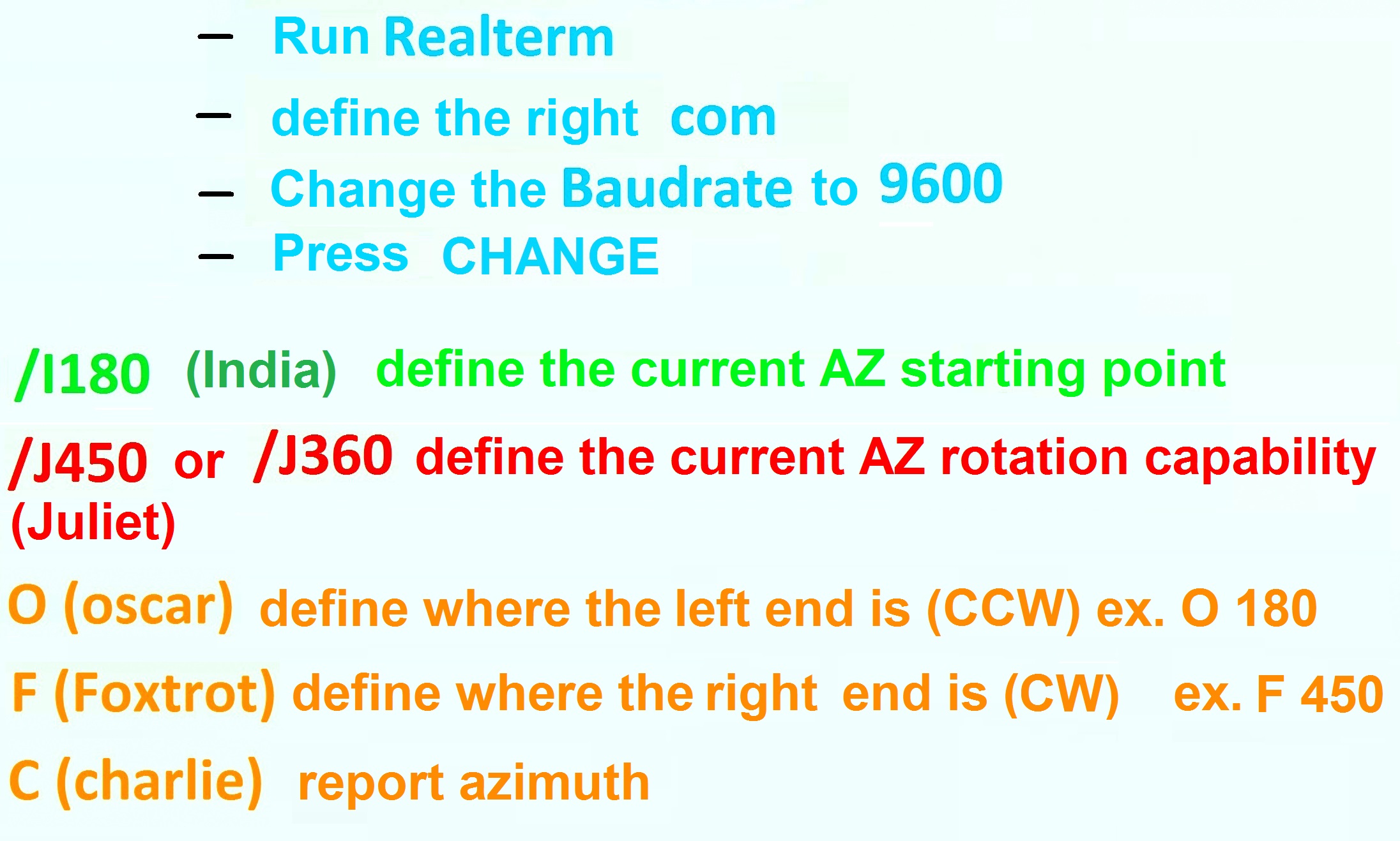
Calibration
Before using the interface for the first time, we must calibrate it, that is, we must tell it where the start is, the end, etc. There is a large set of commands, depending on what we are using and the topic goes beyond this simple presentation. However, if we have a commercially made rotator or a rotator with a potentiometer, we can calibrate it quite simply by using the commands in the image below, and after running a terminal program (eg realterm) to connect to the serial com port created by the arduino.
References
- Site for the K3NG Arduino Rotator https://blog.radioartisan.com/yaesu-rotator-computer-serial-interface/
- The complete manual in English https://github.com/k3ng/k3ng_rotator_controller/wiki
- The latest version of the K3NG software can be downloaded from https://github.com/k3ng/k3ng_rotator_controller
- All the commands that you can use https://github.com/k3ng/k3ng_rotator_controller/wiki/820-Command-Reference
- The K3NG software for rotator control, as configured, setup and used in the SZ1A, can be found at: https://www.qsl.net/sz1a/download/art/sv1elf/k3ng_rotator_controller%20sz1a%20version.zip
In Conclusion…
Do not forget that you can find the latest versions of the software, with more features, etc on the K3NG site. We just offer something simple here to help you start “playing” and in any case something that works out of the box… It is up to you to develop it further…
We are already diving deeper into evolving it more… So we leave the promise: to be continued…