An email and a phone call with my friend Kostas SV1DPI were enough to convince me to share with you my experiences on building an antenna for 50MHz, hoping to motivate you and help you get started! Do not forget that propagation is going up, summer is not far away and the 6m “magic” band will be a real pleasure.
What do we all ask for then?
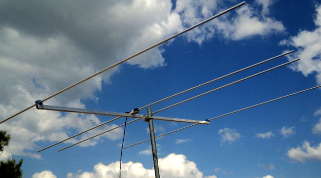
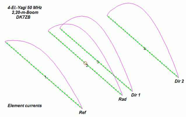
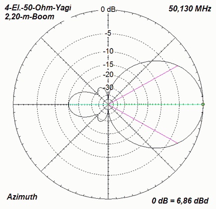
An antenna for 6 meters. That’s how, about 4 years ago, I decided to build an antenna. Searching for a design on the internet, I came across the usual suspect Martin, DK7ZB and followed one of his designs, the 4 Element 50 Ohm Yagi with 2.20m Boom. Martin has many designs for many antennas and you will definitely find what you want.
General description
Let’s look at the construction of the antenna. First, we have a Boom 2.20 meters long which is the backbone of our antenna. That is why we must treat it with absolute respect, because it sustains all the force from the wind and the weather, from warping to whatever one can imagine. We should not, for example, make unnecessary holes because that would hurt its structural integrity.
First of all, we must study the design schematic carefully, pay close attention to detail, and visualize the antenna in our mind. Good practice would be to use a piece of paper and draw the antenna.
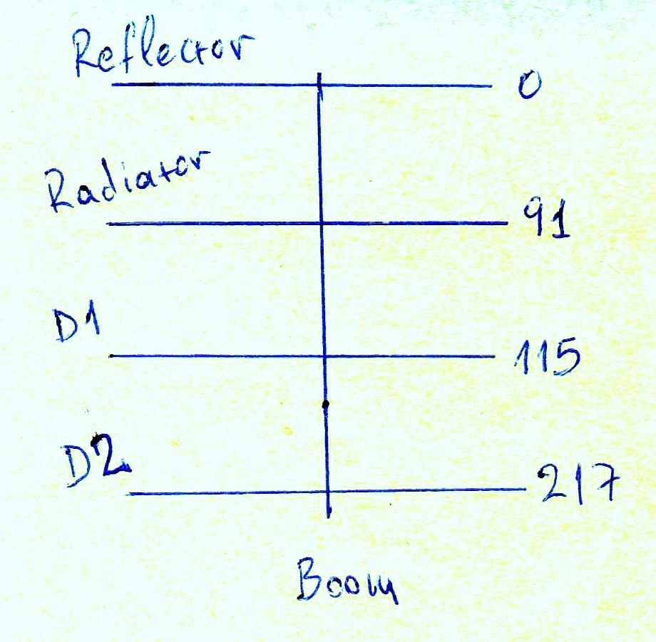
- We draw a vertical line in the middle of the paper which is the Boom and on it we will design our construction.
- Up top, we draw a horizontal line, which will be the beginning, and represents the Reflector and will be the position 0 of the drawing (and the beginning of our measurements). It is the first element of our construction.
- At the Second horizontal line we have the driven-element dipole that we call the Radiator and it is at the 910mm or 91cm position of our design. We will come back later for the details of its construction.
- The Third horizontal line is our first element or rather our first director which we call D1 (Director 1) and is located at 1150mm or 1.15m on the Boom (drawing).
- The fourth horizontal line, which represents our second element, is called D2 (Director 2) and is located at 2170mm or 2.17m.
Many are confused by the naming of the directors and ask why we call them D1 and D2 since the antenna has 4 elements? Each directional antenna has at least one passive element other than the driven element, which is the dipole (we call the ‘driven element’ the element that connects to the feedline). Thus the antenna manages to focus radiated “power” in one direction. It is common for directional antennas to have a reflector, a dipole and at least one director (or more). Depending on the number of elements that we will add and the length of the boom, the antenna lobe will be formed accordingly.
The antenna works extremely well and as a design it is the simplest there is, a 4 Element 50 Ohm Yagi with a 2.20m Boom
Dimensions
Let’s see the dimensions that the antenna should have, according to research done by DK7ZB, in the table below:

We see that the design made by DK7ZB provides different dimensions depending on the aluminium we will use! We are able to use 4 different dimensions in terms of the thickness of aluminium tubing: 12mm – 1/2in – 10mm – 3/8in. Only these dimensions can be used for our elements. Personally, I preferred to use aluminium 12mm and 1.5mm thick to withstand the hardships: wind, birds, snow and other things that man & nature might throw at it. The Boom is 25mm x 25mm x 1.5mm Profil. You will find them in shops with industrial items, blacksmith shops, etc. Aluminium of type 6060 is the best.
Materials
- For the elements
- 1 piece 2.20 m long square aluminium profile, 25mm x 25mm for the Boom
- 1 piece of aluminium tube 12mm, of length 2.94m, for the Reflector
- 1 piece of 12mm aluminium tube, of length 2.82m, for the Radiator (emission dipole) + 2cm for a tuning margin!!!
- 1 piece 12mm aluminium tube, of length 2.76m, for D1 (Director 1)
- 1 piece 12mm aluminium tube, of length 2.72m, for D2 (Director 2)
- For the assembly of the antenna
- 5 Pipe Stauff Clamps (Insulators)
- 4 Ιnox 35mm x 5M allen screws.
- 6 Ιnox 53mm x 5M allen screws.
- 5 Ιnox 34mm x 5M six angle round head screws (Allen Inox Pompe screws)
- 1 Aluminium plate for the antenna’s support on the mast (Boom plate) 14cm x 6cm x 4mm (Width x Height x Thickness).
- 1 Aluminium plate for the support of the Radiator – driven element dipole 14cm x 6cm x 4mm (Width x Height x Thickness).
Details about the materials
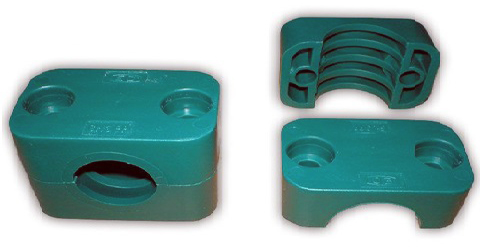
Pipe Stauff Clamps (Insulators)
We find them in stores with industrial items, especially in shops that sell accessories for bulldozers, digging tools, boats, dump trucks, etc. They are used to fasten oil pressure pipes.
Otherwise, we can make them ourselves! How? Using various insulating materials, such as synthetic water pressure pipes. I have tried it on smaller diameter aluminium tubes successfully. The way is as follows:
Purchase a synthetic water pressure pipe with an inner diameter that is the same with the diameter of each element that we have, for example in our case 12mm
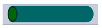
cut it into 5 pieces 7cm long each and then cut the 5 pieces in half with a saw as in the photo.
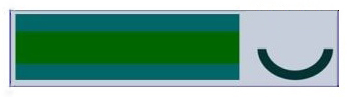
Then we make the crutch base that will fit on our aluminium boom, as in the photo, and “voilà” we have created our own insulators (Pipe Stauff Clamps).


So we’ve solved this part of the construction, which usually concerns most people!
Boom piercing
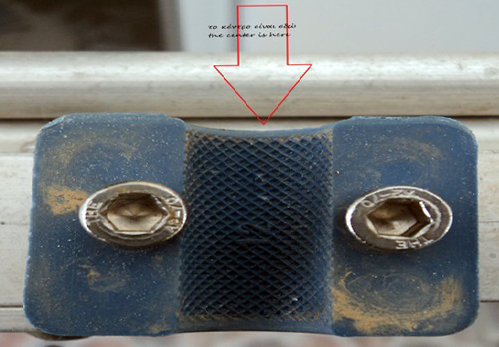
Mark the aluminium boom with a pencil at the distances indicated by the diagram. In our case for 12mm elements, mark near one end for the reflector (point 0), measure 91 cm from there and mark the position of the dipole, 115 cm from point 0 is the position of the 1st director and 217 cm from the point 0 is the position of the 2nd director. Accuracy plays a big role in the proper operation of the antenna! The center is always the center of our tube. Do not forget (especially at the edges) to calculate the thickness of our insulator so that it fits the antenna correctly.
Cutting of elements – Construction of the dipole
We need to know that a good and accurate hole is made in the following way:
- we first mark the point that we will drill with a centering tip
- and then we work with our drills, opening the hole.
We cut the elements of our antenna to the defined dimensions (for 12 mm diameter elements, we have 2934 mm for the reflector, 2750 mm for the 1st director and 2708 mm for the 2nd director), taking care to be accurate.
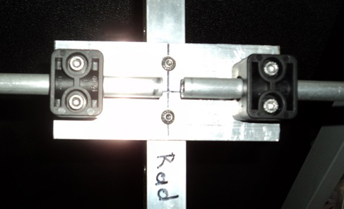
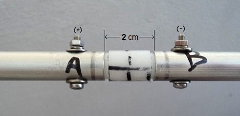
Now let’s get to the heart of our construction, the driven element – dipole (Radiator). For the assembly of the dipole, we will use an aluminium plate for greater stability, as shown in the photo.
According to the manufacturer, we must have a distance of 2cm (or 20 mm) between the two parts of the dipole. This distance is included in the total distance of 2812 mm! So we cut each leg of the dipole (2812-20) / 2 = 1396 mm + 20 mm slack for tuning trimming = 1416 mm for each leg. Attention: we cut the rest of the elements exactly to the provided dimensions and we do not add any length to them.
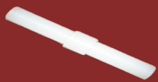
To keep the distance of 2 cm but also for better support of the construction, we use a spacer.
What is a spacer? It’s an insulating component made with a dielectric of Polyamide (Nylon). In this way, we will keep a distance of 2cm between the two sides of the element.
We have now placed all the elements on the Boom and our antenna is almost ready. Check the dimensions again with your tape measure to make sure everything is correct.
It’s now time to connect our feed-line (coax). We drill as shown in the photo to connect our cable – and connect the feed line to the terminals.
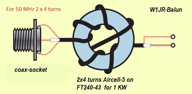
This antenna, if built according to the design, has an impedance of 50 Ohms and can work without a Balun. However, it is good best practice to add a 1: 1 W1JR style Balun, which helps to avoid RF (common-mode currents) returning into our Shack! I assure you that something like this really works. It’s also good practice to place the Balun in a plastic weather-proof box for protection. Again, the Balun is optional for our antenna. For those of you who will use more than 200 Watts (In Greece the permissible power limit on 6m is 100Watts), it is a good idea to build it so that you’ll have peace of mind.
Tunning
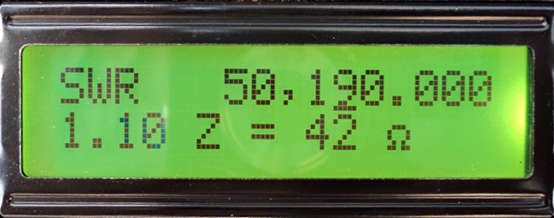
Tuning of the antenna is done by fluctuating the length of the driven-element/dipole radiator (we had intentionally cut it a little longer by 2 cm on each leg, so it will probably need a little cutting to increase the resonant frequency). For this purpose it is convenient to use an Antenna Analyzer and cutting 2-3 millimeters at a time on both sides simultaneously, until we reach the desired result. Try to tune the antenna to the middle of the band in order to have good bandwidth across the entire 50 MHz band.
For the antenna to work properly, it must be placed on a mast of at least 6m height.
In practice…
The antenna works extremely well and as a design it is the simplest there is, a 4 Element 50 Ohm Yagi with a 2.20m Boom. I literally felt wonderfull using it, and enjoyed working, among others, E3 – TR – FG – 4X – 9H – 3A – T7 – 1A0 – S0 and many other prefixes from other countries. I urge everyone to try and build it yourself for one more reason: through the construction process more knowledge about amateur radio is gained. The materials cost only about 50 euros and we will have a “weapon” for DX on our roof. I am sure that you will have fun like me and you will enjoy it since it is an honest antenna that can be placed even on small terraces. It receives well and withstands the hardships of the weather, and above all it is economical. Personally, I bought all the materials for the antenna, except the ferrite, from the store “VIDEMPORIKI” in Chalkida, Greece. I bought the ferrite for the Balun from the store FREEBYTES in Athens, Greece.
I urge everyone to try and build it yourself for one more reason: through the construction process more knowledge about amateur radio is gained
I hope I have helped you overcome any worries you might have had, and that you start, with the help of the photos I’ve posted, to build your first antenna for 6m.
73 and good dx to all!
Dimitrios – SV8LMQ