By Ian VK3BUF - Published in the September 2021 Edition of QTC
As long as radio has existed there have been wire antennas. These have been made from a diverse range of conductive materials. Often the selection criteria comes down to price, weight, availability, and strength, rather than RF efficiency.
There has been no shortage of controversy, theory, and anecdotes about which type of wire is best suited to antenna construction. Trial data on this topic is difficult to find.
There are questions about other properties, such as the effect of plastic coatings on wire and the merit of single versus multi-strand wire. What about the strength of stainless- steel versus the high conductivity of hard drawn copper?
The big question remains…..Which wire should I use to build my HF antennas?
We decided to road-test a selection and find out which material performed best in the field. Fundamentally, we wanted to see how received signals varied from a low-power signal transmitted from different antenna wires.
What’s in a wire?
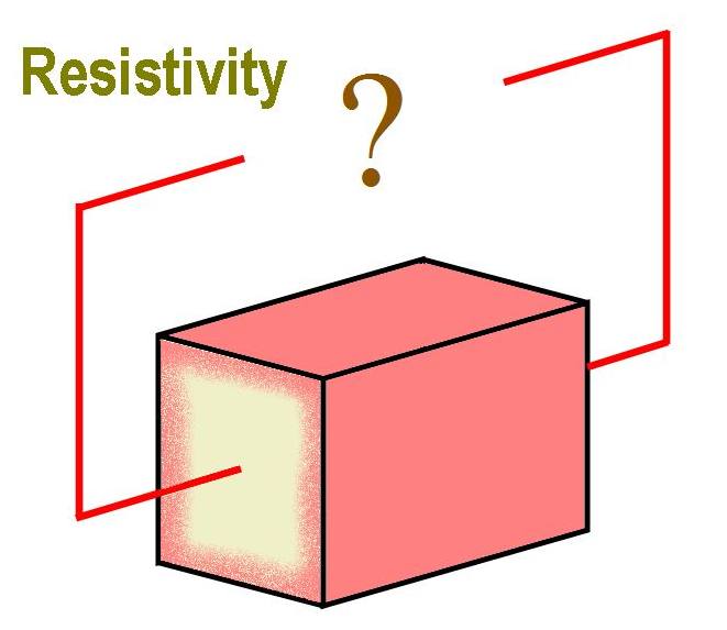
Different metals have a different intrinsic resistance, or ‘resistivity’. A high resistivity will suppress RF current flow and dissipate this precious energy as heat. Resistivity tables tell us that copper is a great conductor, up there between gold and silver, while steel has around three times the resistance.
The ever-popular wire of choice for many commercial and amateur HF antennas, stainless steel, has an even higher resistivity.
Looking only at these passive resistance tables, one could conclude that using any conductor other than copper would be a poor choice. However, there is much more to this story at radio frequencies.
When wire is created there are surface tempering effects within the metals. Resistance is not always even through a cross section of wire. At radio frequencies there is a tendency for currents to flow on the surface of conductors rather than through the centre. This is called ‘skin effect’ and it becomes more pronounced as the frequency increases.
This means that at 160M and 80M the RF penetration into a wire conductor will be deeper than for higher bands.
This will have some effect on the total radiation resistance for any given type of wire.
“Skin Effect” applies to each individual conductor. Wire made up of several thin conductors instead of one larger conductor has the equivalence of several parallel conductors.
This increases the amount of skin effect, further lowering the wires overall resistance.
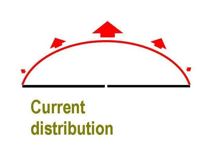
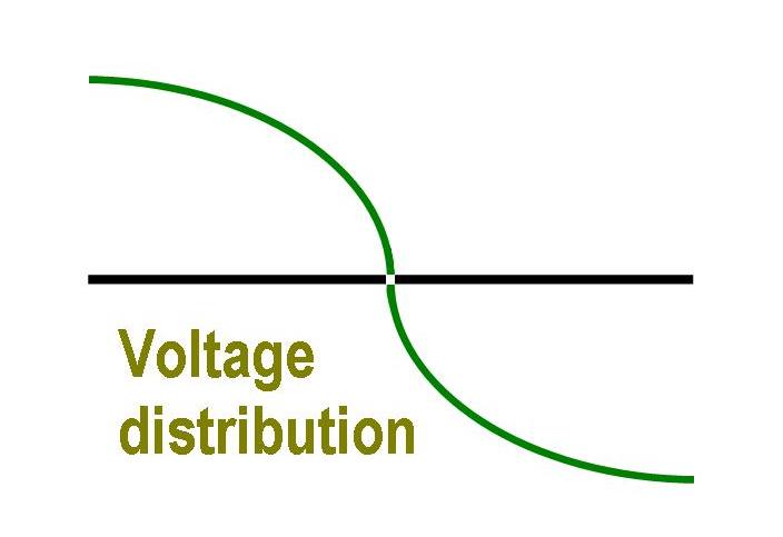
RF currents behave differently to conventional DC electrical current flows. There are voltage and current distributions along the length of an antenna. Current flows are not even. In a basic Dipole antenna, the voltage potential rises to a maximum at the ends, while current distribution is greatest at the feedpoint. Most of the RF current flow in a dipole never reaches the ends of the wire.
This current distribution is also one of the reasons why top-loaded mobile antennas generally out-perform base loaded mobile antennas. The section of maximum current radiation in a base loaded vertical will also be subject to greater radiation resistance due to the presence of the loading coil. Unfortunately, top-loaded antennas tend to be top-heavy, an unwanted design characteristic in a mobile antenna. Physical design compromises are common with many antenna designs.
Designing the experiment.
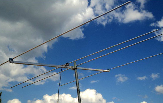
Differences in signal strengths between the various conductors was likely to be subtle. For simplicity, we decided to perform these tests with dipole antennas on the 15 metre band.
Being at the high end of HF, the skin effect would be more pronounced. If the skin effect was going to be significant for our experiments, then we would more likely see any differences on 15 Metres than on lower frequencies.
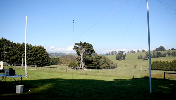
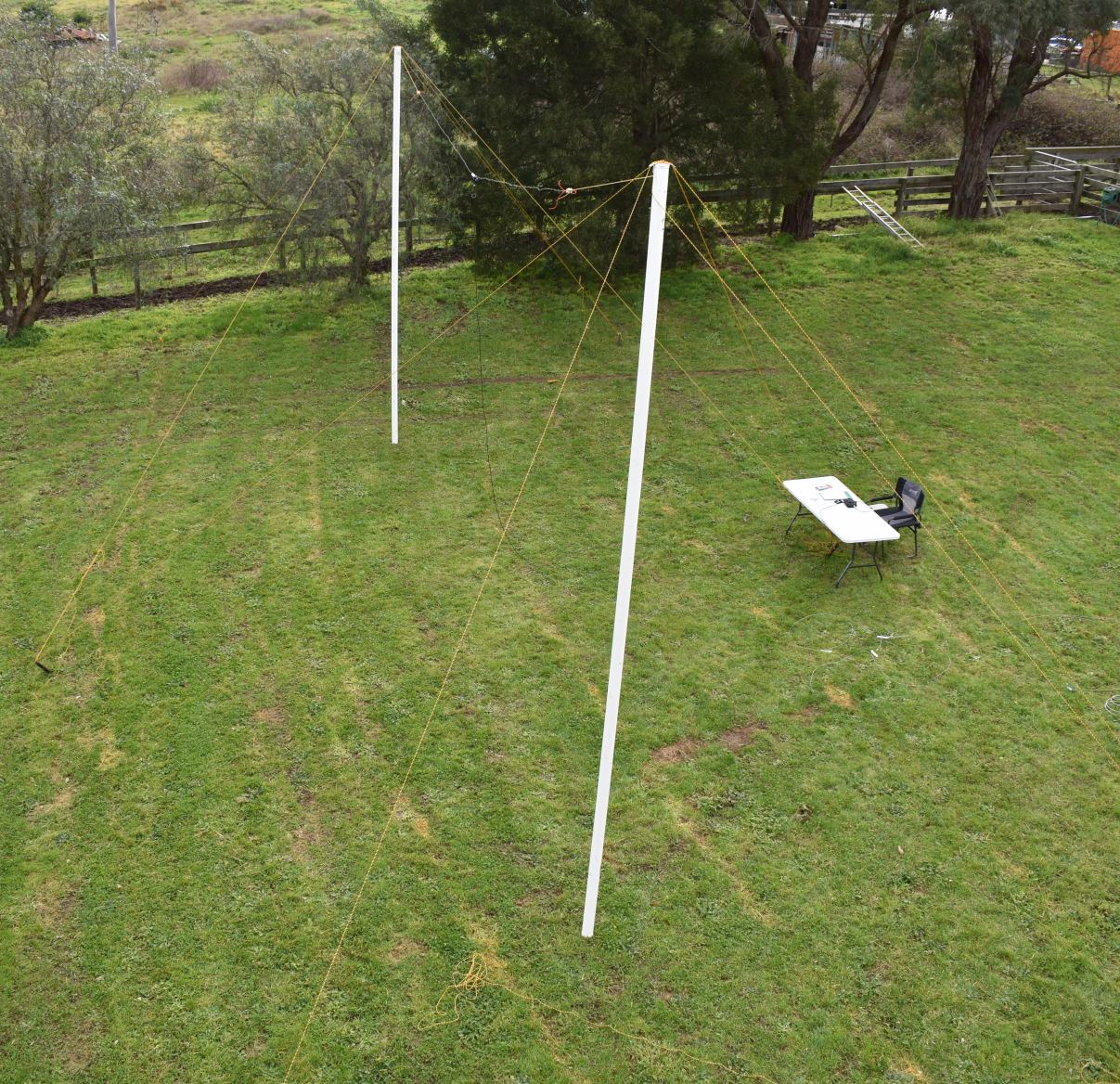
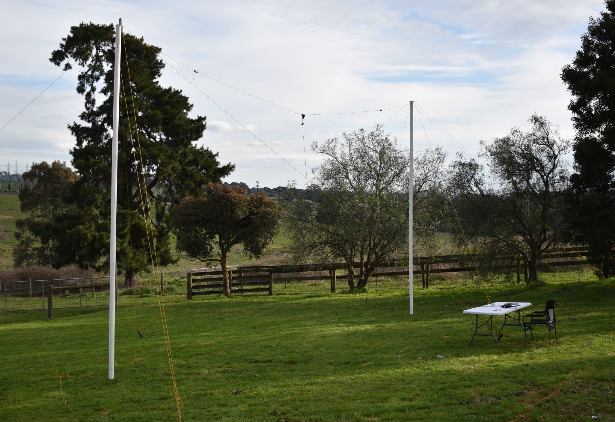
We needed a suitable test environment with the distance between the transmitter and receiver being appropriate. We wanted to minimise external disruptions, such as multi- pathing, polarisation shifts and unwanted reflections.
The objective was to provide a weak but stable signal transmitted from each of the test antennas and received signals to be measured several wavelengths away.
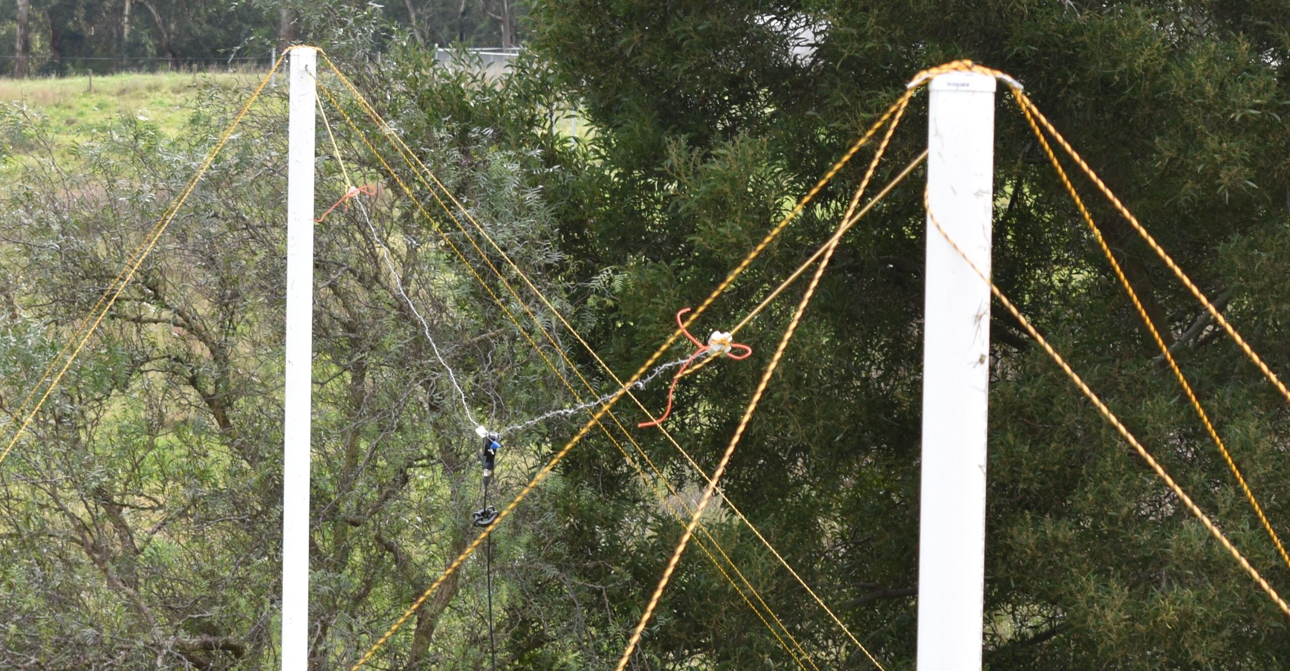
A pair of 6m tall PVC posts were erected, guyed with plastic rope to create a reasonably RF transparent structure. Just over 200 metres away two more posts were set up for the receiving antenna.

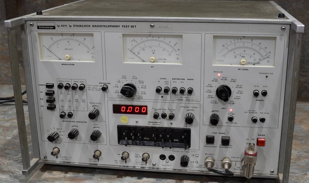
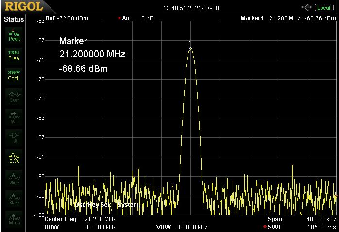
For a transmitter we used an RF signal generator (Shlumberger 4011 test set), producing about one milliwatt of un- modulated RF energy on 21.2 MHz. By testing at these low levels, the receiver would not be overloaded and our test signal would not be disruptive to others.
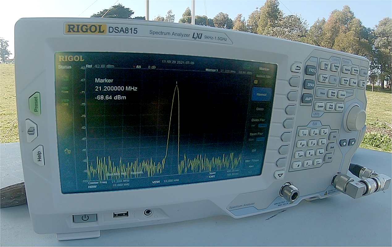
For a receiver we used a Rigol DSA815 spectrum analyser. The receiver monitor produces a signal spike where fractions of dB changes in signal strengths are easily measurable.
The Rigol spectrum analyser is more accurate than an S-meter on a HF radio. Most modern HF rigs use segmented bar graphs that lack fine resolution.
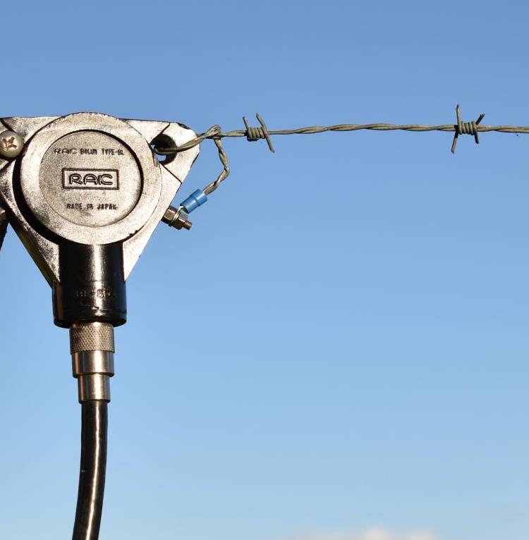
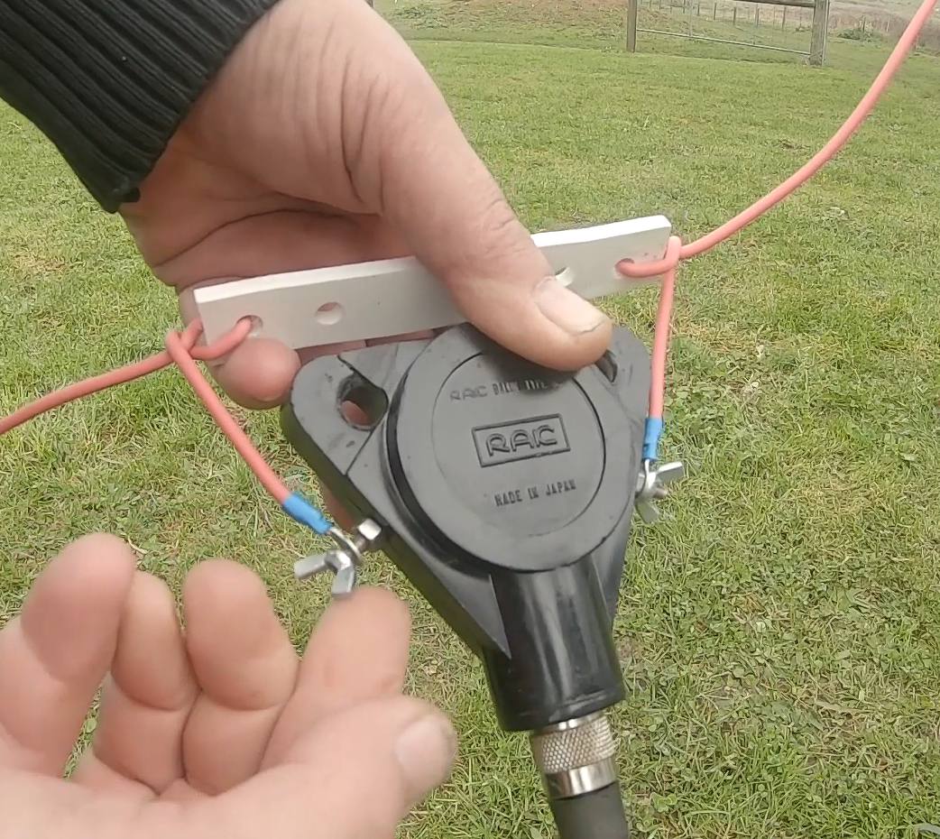
Ten dipoles, made from different conducting materials were constructed. Each dipole would be coupled to a 1:1 balun at the feed point. They would be tied to ceramic insulators to ensure the supporting ropes would not influence the tests. A differentially wound ferrite ring was added under the balun to reduce the possibility of RF currents being radiated by the coax feedline.
The feedline at both the transmitter and receiver was 7 metres of RG58 coax.
We were now ready to measure some signals…
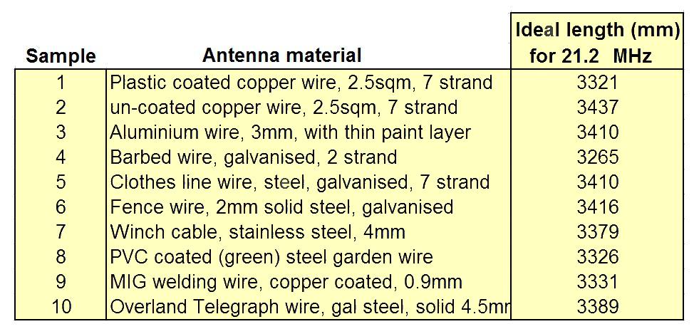
Meet the antenna samples:
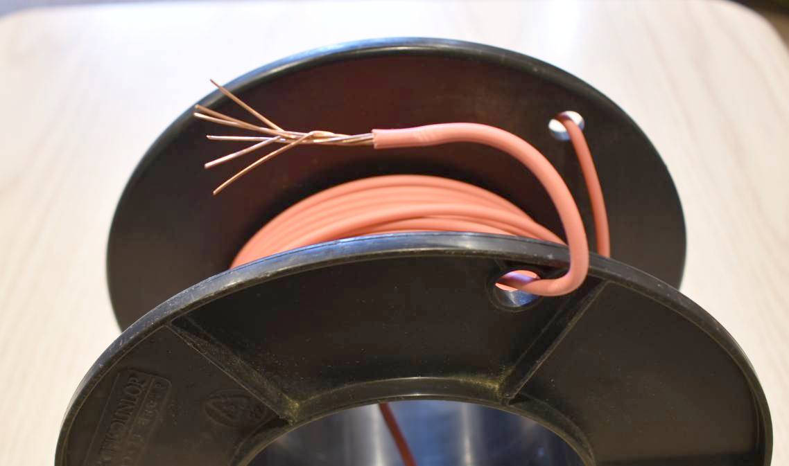
Antenna #1 and #2 – Copper wire
Perhaps the most common wire used in antennas is copper ‘building’ wire. This is PVC plastic coated wire, seven strand, 2.5mm. It is the sort of product that most low-current electrical switchboards use. It is reasonably inexpensive and moderately tough.
There is often speculation that the PVC coating on the wire will affect antenna performance. We wanted to put this speculation to the test. Hence two dipoles were made from the same reel, but one had its PVC coating stripped off, leaving the shiny 7-strand wire fully exposed.
The plain copper dipole became Antenna #1 and its PVC coated counterpart became Antenna #2. A third one was made to use as the receiving antenna.
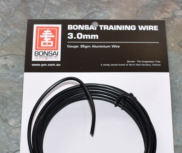
Antenna #3 – Aluminium wire
We were keen to introduce aluminium into the mix, as there has been much speculation on the suitability of this alloy as an antenna conductor.
Locating a reliable source of aluminium wire was difficult, but the local hardware store stocked 3mm aluminium wire for helping growers to shape Bonsai trees.
While it was expensive, it was soft, light, easy to work with and had a thin protective coating to reduce corrosion.
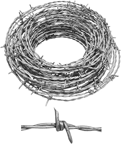
Antenna #4 – Barbed wire
Some two-strand barbed wire was chosen for this antenna.
It is a galvanised high- tensile steel that is tough and had to be trimmed with bolt-cutters.
While there is plenty of it around, it was not the most pleasant wire to work with. It was included in the test to see if its high-tensile characteristic would have any effect at radio frequencies.
There have been stories of Amateurs insulating and using boundary fences as radiators!
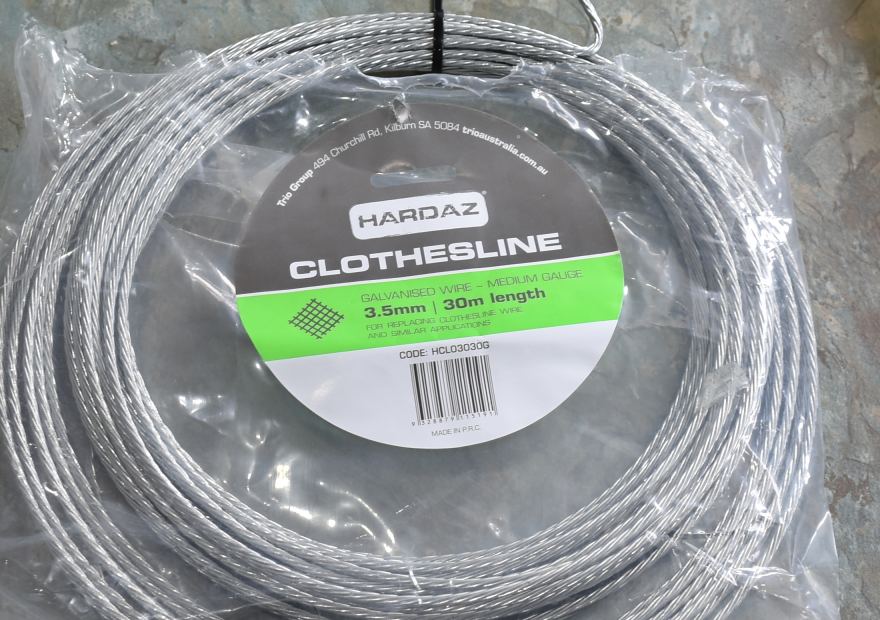
Antennas #5 and #6 – Clothesline wire & fencing wire
Both of these were galvanised steel. Wire #5 is a multi-strand wire sold as ‘clothesline wire’ and is often used as guy wire for masts.
Wire #6 was non-barbed fencing wire, 2mm in diameter.
Both types were included to see if there was any measurable difference between multi-core and single core conductors.
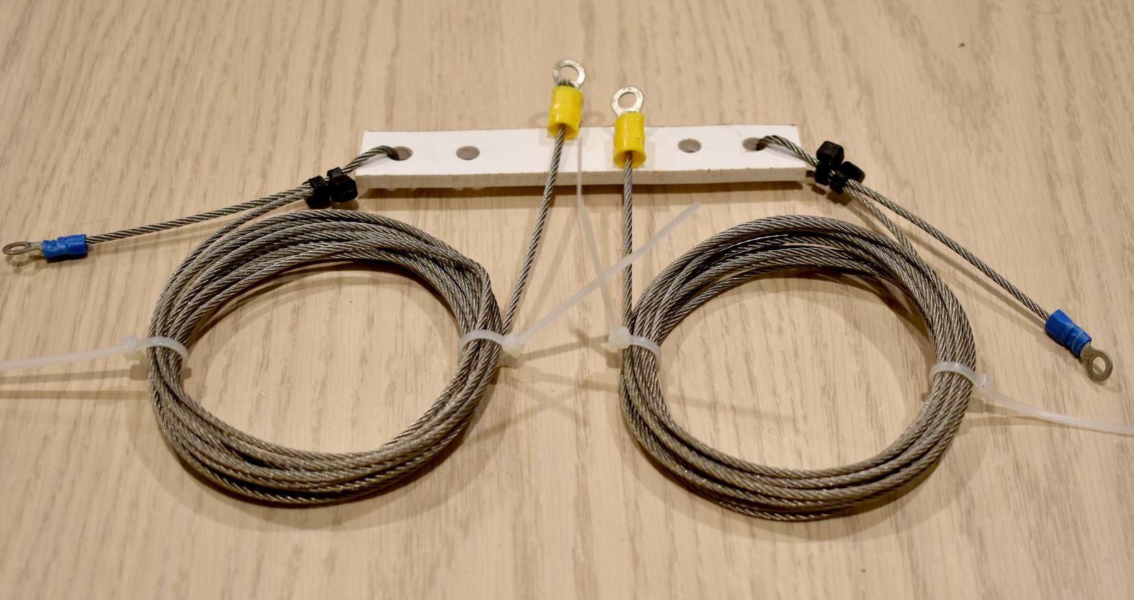
Antenna #7 – Stainless steel cable
Often used for balustrades and shade sails, this stainless-steel cable has a reputation of being tough and weatherproof in harsh environments.
It is a worthwhile addition to the test because of its endurance, particularly in costal areas and maritime scenarios.
We were curious to see how well it would perform at radio frequencies.
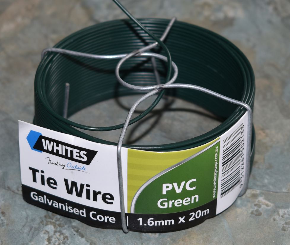
Antenna #8 – Garden tie-wire
This is somewhat similar to fencing wire, except that it is thinner and has a green PVC plastic coating.
It is cheap and reasonably easy to work with.
This wire has been included in several antenna construction articles, and its use has attracted some criticism.
This was a good opportunity to see if it was as bad as some profess.
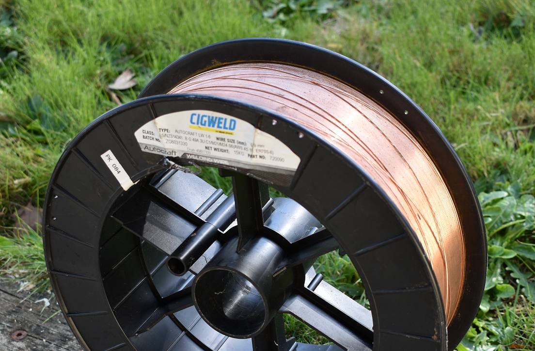
Antenna #9 – MIG welding wire
This type of wire is cheap and plentiful, but it has some issues. It has a solid steel 0.9mm core with a thin copper coating, designed to be used in welding machines. It is very strong, but hard to work with.
In 2016 we used MIG welding wire to make a rhombic antenna for the 40-metre band, spread over 5 acres on top of 12 metre high posts.
It seemed to work well at the time, but even after just two weeks in the air there were some signs of surface corrosion.
Would the copper coating help at radio frequencies?
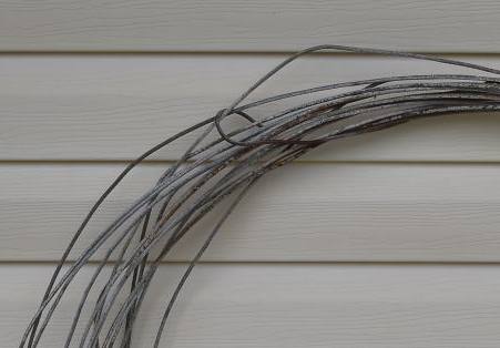
Antenna #10 – Overland Telegraph wire
In 1872 an overland telegraph line was constructed between Adelaide and Darwin, some 3,200km long, through some inhospitable land. Whilst it was a commercial success, it was expensive to use, with each Morse Code word sent costing the equivalent of a day’s wages for a labourer.
The original path went through Oodnadatta, next to the old Ghan rail route. In 1995 I found long sections of wire laying on the ground between sand dunes, well preserved in the dry climate. I rolled up enough to make a couple of 80 metre dipoles and lashed it to the roof rack. I had heard stories about steel wire being unsuitable for antennas, so in the end I was reticent to use it. These tests provided the ideal opportunity to see if my concerns were warranted.
It is a very stiff, heavily galvanised wire, about 4.5mm in diameter.
Checking for resonance
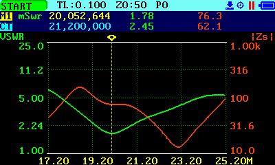
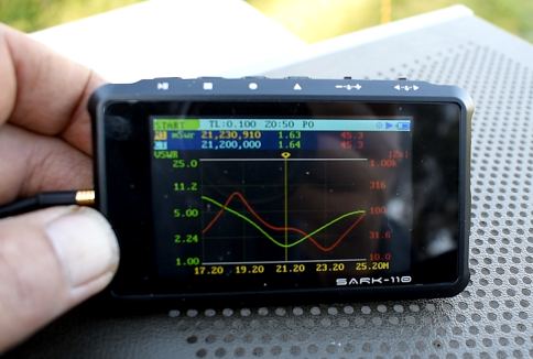
For these tests, antenna resonance was important. We didn’t want results skewed by reflected power from a poorly matched load. We used a SARK110 antenna analyser to check VSWR of each test antenna. The results were surprisingly diverse.
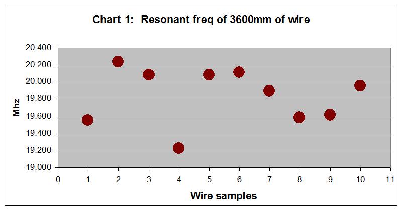
The same antenna lengths (with each conductor type) gave resonant frequencies varying as much as 1 MHz.
Even with the first two samples, removing the PVC coating from the copper wire increased resonant frequency by 700 KHz. This is an important characteristic for experimenters to note, as it will impact many other antenna designs.
The table below shows the results with each antenna was trimmed to resonance.
These figures worked well and when re- tested, each antenna had a peak resonance centred right on our test frequency.
An important observation here was the variability between copper wire with and without PVC insulation. The metal used in each antenna also affected antenna length, with the biggest difference being 172mm per leg.

The tests
The testing proceeded smoothly, with liaison between the two stations taking place via 2M hand-helds.
The signal generator produced a stable RF signal, easily received and measured with a marker point on the spectrum analyser. These measurements provided clear indicators as to how well each antenna performed under test conditions.
Reception was also checked with an old FT- 101 transceiver, as these had an analogue S-meter, but the signals were low and small differences were difficult to discern.
It took about four hours to complete the tests, with the final test looping back to the first antenna to ensure that nothing had changed with the test environment over the course of the day.
The tests were recorded by video and posted to the RASA YouTube channel.
Conclusions

The findings of these tests may surprise some.
Others, who have been using dipoles made from varying materials will be less surprised.
The type of wire used has only a small effect on the radiated signal strength. With the exception of MIG welding wire, the other nine wire types fell within a 2dBm range. That’s barely discernible; about one-third of an ‘S’ point on a regular HF receiver.
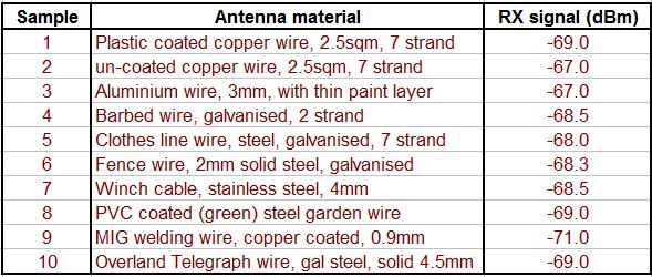
This image shows the variations between all ten wire samples.
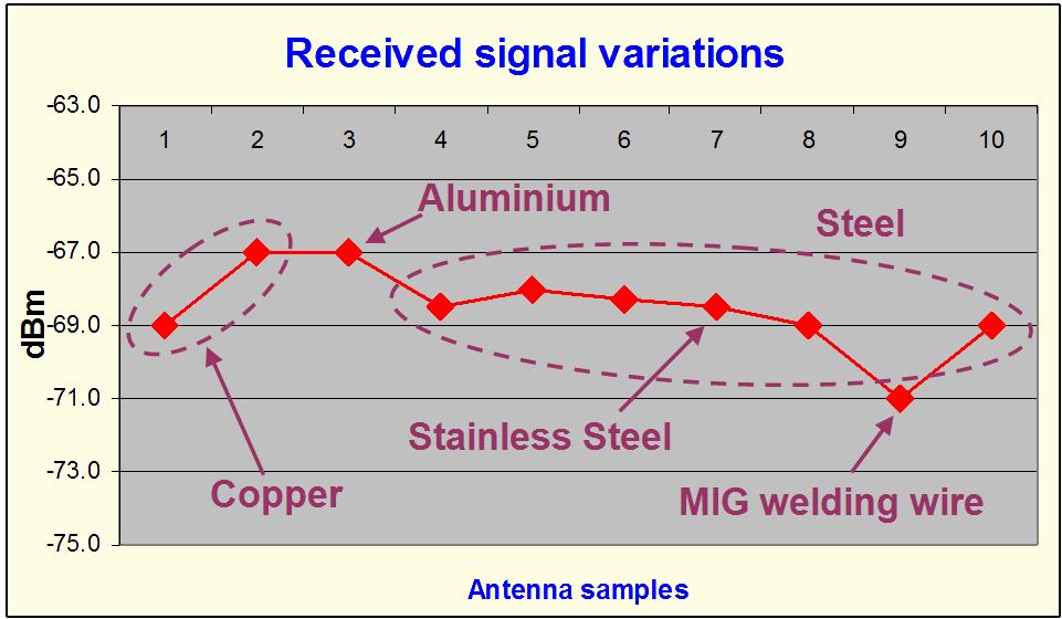
The main conclusions were:
- The type of wire used has only a small effect on the radiated signal strength. With the exception of MIG welding wire, the other nine wire types fell within a 2dBm range. That’s barely discernible; about one-third of an ‘S’ point on a regular HF receiver. The table below shows the results.
- The choice of conductor and its insulation will influence the antenna length and feed-point impedance. Removing the PVC insulation from a multi-strand copper cable increased the resonant frequency by 0.7 MHz and lowered the impedance by 10 ohms.
- Other than adjusting the length to resonance, there is little cause for concern over the type of wire used in a dipole. Effective differences are minor. The cheap galvanised clothes-line wire performed nearly as well as the more expensive copper and aluminium wires. It is more important to focus on other practical characteristics, such as strength, reliability, height, and orientation.
- The toughest and most flexible of all the wire tested was the thin stainless-steel cable, making it the best overall choice of antenna wire for all conditions. (Editor: Anecdotal experience supports this assertion. Many successful HF stations use stainless steel as the preferred material for wire antennas.)
It is important to note that these tests were experimental and hands-on in nature. We were not seeking a specific outcome. Whilst it would have been nice to expand the experiment to include the 40 or 80 metre bands, or try other antenna designs, time and space were limited.

Readers who have conducted similar tests and wish to share their own experiences are invited to do so.
Effective differences are minor. The cheap galvanised clothes-line wire performed nearly as well as the more expensive copper and aluminium wires.
Finally, don’t use barbed wire as an antenna. It performs ok, but it’s terrible to work with.
(Editor: An alternate study using software EZNEC Pro2 modelling to base its findings, does not recommend the use of Stainless-Steel wire. The article can be found here.)
Disclaimer: These tests and findings are presented in good faith. Your experience may be different.
Want to see a video of these antenna wire tests? Click here to watch our YouTube video.