Recently I have noticed that there is a lot of interest in the amateur radio community regarding baluns-chokes with ferrites, the placement of which is intended to reduce returned and unwanted RF.
Introduction
Most of us are familiar with the term “RF in the shack“. Serious problems have obvious symptoms. RF burning may occur when touching a chassis or a button. There may be strange equipment behavior, such as distortion and equipment locking up. Smaller problems on the other hand are often not very obvious. This unwanted “coupling” can transfer noise to the antenna and one might assume that the noise is normal and unavoidable. Unwanted RF currents also waste power that would otherwise be radiated as a useful signal and we are probably not aware of the extent to which it actually occurs.

In an ideal world, RF flows around the outer surface of the coaxial center conductor and returns via the inner surface of the shield. When there is an imbalance in the antenna (for any reason), current will flow on the outer surface of the shield. This may not seem possible, but it is important to remember that, unlike DC, RF current does not flow through the conductors, it flows on the surface of the conductors. The current flowing on the outer surface of the shield is the unbalanced current that does not return inside the coaxial cable. The phenomenon is called Common Mode Current.
This leads to a very important question. If the current doesn’t return internally via the cable, where does it go?
The answer is, it radiates!
In fact, the amount of radiation (RF) from the coaxial cable is proportional to the common operating current flowing through that cable.
Practical Guide
The purpose of building a measuring instrument for common-mode currents for HF and not only our antenna system is for:
- the detection and measurement of return current (CMC), if any
- the effectiveness of baluns and chokes
To begin with, remember that the common-mode current is that element of the unbalanced current that flows in a transmission line and in the case of a coaxial line, it flows entirely and exclusively on the outer surface of the outer conductor (ie. on the outer surface of the shield).
The basic idea is be able to inductively couple to the outer shield of the coaxial cable using a split-bead ferrite, in which we wind wire creating a coil, and to inductively measure any current on the outside (shield) of the cable.
Materials that we will need:
- A large plastic peg such as those used for camping or similar (large enough to clamp on the coax), or, alternatively a small plastic box
- One 47Ω Resistor
- One Schottky diode (or a simple 1N4148 diode)
- One 4,7nF Capacitor
- A 10 KΩ Resistor
- A Potentiometer or Trimmer 1K (resistance and the potentiometer values are not critical and depend on the scale of the measuring instrument you choose)
- Some thin insulated wire (ie from UTP cable), or, enamelled magnet wire up to 0,8 mm thick (enough for 10 turns)
- A small-scale instrument 50 to 1000μA
- A split-bead ferrite such as the snap-on type
- And optionally a switch
The values of the materials are not critical – you can use whatever you have on hand, most likely with good results.
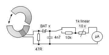
The operation of the circuit is simple:
When transmitting, the current flowing on the outside of the coaxial cable (on the outside of the shield) creates a potential that inductively appears in the coil which is wound on the ferrite. The induced current is then rectified by the Schottky diode and displayed as an indication on the instrument.
The optional switch is used to select measurement scale, one for low and one for high power, while the potentiometer adjusts the sensitivity of the instrument.
You do not need to calibrate the instrument, you can make a good measurement with a non-calibrated instrument.
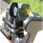
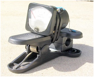
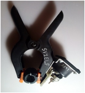
RF CMC Meter Split Ferrite on Clamp 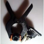
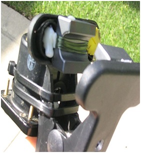
RF CMC Meter – Side View of components 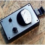
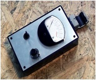
RF CMC Meter – Front View
Measurement of common-mode current (cmc) does not need to be made at full power.
With this method, you will have an indication of what is happening on the transmission line to your antenna, but it will not offer you a highly accurate result.
To confirm that CMC currents are low or non-existent, the line must be checked at various distances, at least at two or more points.
Dealing with unwanted RF
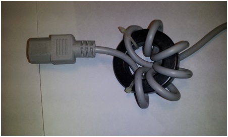
After testing, the next step is to install a choke to limit unwanted RF. The choke is nothing more than a ferrite, with a few turns of coaxial cable running through it. The ideal type of ferrite is made of Mix 31 or 43. Many ferrites can be used in parallel for better results (as shown in the photo).


Alternatively, tubular or split bead ferrites may be used along the transmission line.
Place the current balun or common mode choke in the correct position along the transmission line, usually close to the antenna feed point, to minimize common-mode current.
Below, is a very good table created by G3TXQ with performance information of various common mode choke designs:

Radiated RF can cause problems with computers and other electrical appliances that we have in the shack
Radiated RF can cause problems with computers and other electrical appliances that we have in the shack, in this case supplimental installation of ferrites on 230v or 12v power cables is necessary.
In conclusion, I would like to point out that this build is a simple instrument that we must have if we want to know the effect that the installation of ferrite-chokes has on the elimination of unwanted RF, and also for their correct placement at the selected places which result from our measurements.
I would also recommend reading this article on the proper use of ferrites.
Good luck!
Bibliography
- https://www.dxengineering.com/techarticles/balunsandfeedlinechokes/balun-basics-common-mode-vs-differential-mode
- https://www.w8ji.com/common_mode_current.htm
- https://owenduffy.net/module/icm/index.htm
- https://www.dj0ip.de/cmc-test/
- https://forums.qrz.com/index.php?threads/measuring-common-mode-current.623054/page-2
- https://ham.stackexchange.com/questions/1271/how-to-detect-common-mode-currents-or-rf-in-the-shack
- http://www.k0bg.com/common.html
- https://qrm.guru/the-truth-about-ferrites/
- https://gm3sek.files.wordpress.com/2019/01/G3TXQ-RC.pdf