Introduction to the Decibel (dB)
The definition of the bel was derived from measurements in telephony on the Bell system in the United States in the early 20th century. The bel (B) was named in honor of Alexander Graham Bell, but the bel is rarely used.
Contents
In its place, the Decibel (dB) is used instead, which is one-tenth of a bel, and follows a logarithmic scale in which the level difference between physical quantities is expressed.
Especially when it comes to sound, human perception is logarithmic, so the dB is better suited to how we perceive differences in audio levels.
In electronics, amplifier gain, signal attenuation and signal-to-noise ratios are expressed in the Decibel (dB).
Our daily use of the dB thus raises the need to look at it a little closer.
What exactly is it? how is it defined? and how can we use it with full knowledge of the relationships and quantities we are referring to?
The Logarithmic Nature of the dB
The decibel (dB) expresses the decimal logarithm of the ratio of two quantities.
The use of Decibels (dB) allows the transformation of very large or very small numbers into more manageable values through logarithms. This means that instead of working with huge values of power, voltage or current, we can use the corresponding logarithmic ratios, making calculations easier and more understandable.

Basic Logarithm Definitions
Here we should open a parenthesis, which is necessary to recall what a logarithm of a number is and some simple properties of logarithms which will be useful in the analysis below.
A decimal logarithm (log) of a number A is a number X which, if taken as an exponent of 10, will give us the number A. e.g. log A=X if 10x = A. The number 10 is called the BASE of decimal logarithms.
So, for example, the logarithm of 100 is 2 because 102 = 100, of 1000 is 3 because 103 = 1000 etc.
The decimal logarithm is denoted by the symbol log so the logarithm of, let’s say, the number 2, is denoted as log2.
Some properties of logarithms are that the logarithm of a product is equal to the sum of the logarithms of the terms of the product, e.g.
log (AB) = logA + logB.
The logarithm of a fraction is equal to the difference between the logarithms of the numerator and denominator, e.g.
log A/B = logA – log B
The logarithm of a power is equal to the product of the exponent times the logarithm of the base, e.g.
log Ax = x logA
Closing this short parenthesis, which was intended to remind us a little of our younger years at the school desk, let’s look at the relationship between decibel (dB) and power and voltage.
dB and Power
The various devices through which a signal passes, such as amplifiers, attenuators etc. can be considered as a quadripole, i.e. individual devices (black boxes) that have two terminals at the input and two at the output.
If we feed the input of such a quadripole with a signal of a certain level and measure the level of this signal at the output of the quadripole, then if the signal is found to be greater than what it was at the input the quadripole is said to amplify, otherwise the quadripole attenuates. The level of such a signal can be expressed in terms of power ( P ) or voltage ( V ). The basic formula which relates the decibel to power is:
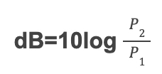
(relation 1)
Where P2 = signal power at the output of the quadripole and P1 = signal power at the input of the quadripole.
The constant 10 is derived from Fechner – Weber’s law:

(law of psychophysics, describing the relationship between the physical intensity of a stimulus and the perceived intensity of that stimulus by humans, where for technical applications the constant is C = 10).
Power Examples
If we apply a signal P1 = 10W to the input of the previous quadripole and measure at the output P2 = 100W, then applying relation 1 we have:
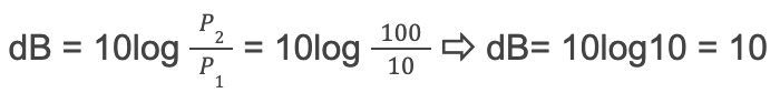
because the logarithm of 10 is 1 (log10=1), thus we have an amplification of 10dB.
But if the power of input P1 = 100W and the power of output P2 = 10W then we will have:

Thus, we have an attenuation of -10dB.
Now if in the previous quadripole the power of the output is double the power applied to the input i.e. P1 = 10W and P2 = 20W then we will have:
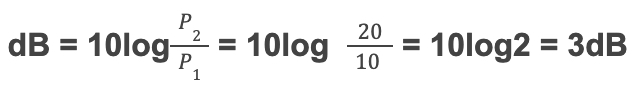
(because log2=0.3).
Thus for every 3dB we have a doubling of power and for every -3dB we have a reduction by half.
Each time we increase the gain by 3dB we can see how many times the output power becomes greater than the input power of our quadripole for example:
3 dB → 2 times
6 dB → 4 times
9 dB → 8 times
10 dB → 10 times
13 dB → 20 times
16 dB → 40 times
19 dB → 80 times
20 dB → 100 times
…for every 3dB we have a doubling of power and for every -3dB we have a reduction by half.
dB and Voltage
If in place of the powers P1 and P2 at the input and corresponding output of the quadripole we measure the voltages V1 and V2 instead, then relation 1 takes the form of:
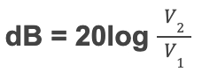
(relation 2)
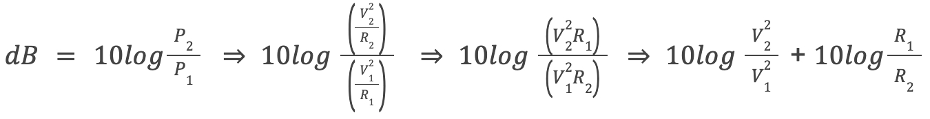
Relation 2 is derived from relation 1 as follows. We know that the power P consumed by a resistor R when a voltage V is applied across the ends of this resistor is equal to P = V2 / R (Ohm’s law).
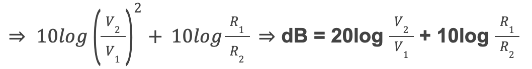
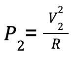
If in relation 1 we substitute the power symbol with what we just mentioned above, then we will have:

The analysis of this relationship shows that the two voltages were measured across equal resistances. However, if the resistances over which the voltages are measured are not equal, then we will have:
Voltage Examples
If we now apply to the input of the previous quadripole a signal with an amplitude of 10 Volts and get at the output the same signal with an amplitude of 20 Volts then by applying relation 2 we will have:
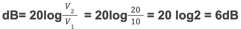
(because log2=0.3).
Therefore, in the case of Voltage, for every 6dB we have double, and for every -6dB we have a reduction by half.
Each time we increase the amplitude of the input signal by 6dB we can see how many times the amplitude of the corresponding output signal of our quadripole increases, for example:
6dB → 2 times
12dB → 4 times
18dB → 8 times
20dB → 10 times
26dB → 20 times
32dB → 40 times
38dB → 80 times
40dB → 100 times
…in the case of Voltage, for every 6dB we have doubling, and for every -6dB we have a reduction by half.
Computational Caveats
With the dB we can perform any arithmetic operation, but we have to be careful and use caution because we can easily get wrong results.
I will immediately provide an example below to make it easier to understand how we can be led to wrong results.
What is the average of 10dB and 20dB in terms of power?
If we answered 15dB we are wrong!!
The correct way to think about it is this; If we want to find the average in dB, we must first take the arithmetic mean of the actual power values and then convert it to dB.
We know that:
10 dB = 10 times the reference power
and
20 dB = 100 times the reference power
Therefore:
Avarege = (10+100) / 2 = 55
Now, convert this Average to dB, and we have:
dB = 10log55 = 17.4
(because the logarithm of 55 is 1.74).
So, the correct answer to the question “what is the average of 10dB and 20dB” is 17.4dB.
(The wrong answer of 15dB = 31.62 times the reference power, a value that can in no way be the average of 10 and 100).
Conclusions
From what we have said so far we should remember three fundamental conclusions.
- The decibel (dB) represents the relative difference between the levels of two points within a system. It is a ratio, not an absolute measurement. Therefore, the dB is NOT a unit of measurement but rather a way to compare levels within the same system.
- For power every 3dB is double the power and every 10dB is a tenfold increase. While every -3dB is half the power and every -10dB a tenfold decrease.
- In voltage, every 6dB is double, and every 20dB is a tenfold increase, while every -6dB is half, and every -20dB is a tenfold decrease.
…the dB is NOT a unit of measurement but rather a way to compare levels within the same system.
Absolute Levels (dBm, dBV)
Sometimes in measurements or various calculations, we need to be more specific about a level we are measuring or calculating. For this reason, a reference level may been defined, against which each measured level is compared. For power this is 1mW which is expressed in dBm (dBm means dB in relation to 1mW) and is conventionally called the zero level. 1mW = 0dBm is because:
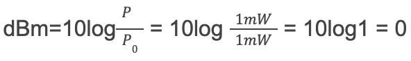
(because the logarithm of 1=0)
The value obtained by comparing any level with the 1mW level is called the absolute level.
The absolute level can also refer to a voltage level. It is measured by comparing it to 775mV, which defines the zero level. This is because 775mV across a 600Ω resistor generates 1mW of power (600Ω was a typical resistance value in telecommunications and audio circuits, as it was widely used in analog audio transmission lines).
So the absolute power and voltage levels expressed in dB are as follows:
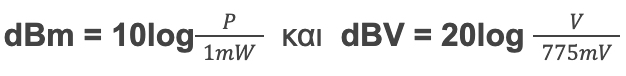
The dBm and dBV ARE units of measurement because the comparison is made towards the fixed and specific values of 1mW and 775mV, respectively.
Let us now see how we can express one absolute level as a function of the other.
If, for example, the measured voltage V across an impedance Z and the measured power is P then we will have P = V2/Z (ohm’s law) but we know that between absolute voltage and power there is the relation:
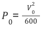
where P0 = 1mW and V0 = 775 mV
If we divide the two previous relations by their members, logarithmize and multiply both members of the relationship by 10, we obtain:
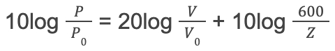
However, we know that 10log(P/P0) is the absolute level of power (dBm) and that 20log(V/V0) is the absolute level of voltage (dBV). So the previous relation becomes dBm = dBV + 10log ( 600 / Z ).
From this relationship, it can be derived that:
| At Impedance Z = 600Ω → dBm = dBV |
| At Impedance Z = 300Ω → dBm = dBV + 3dB |
| At Impedance Z = 150Ω → dBm = dBV + 6dB |
| At Impedance Z = 75Ω → dBm = dBV + 9dB |
| At Impedance Z = 50Ω → dBm = dBV + 10dB |
The dBm and dBV ARE units of measurement because the comparison is made towards the fixed and specific values…
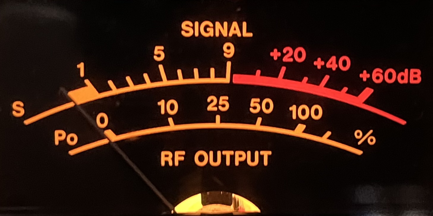
S-Units and their relationship to the Decibel
The S Unit, or signal strength unit, is a standard measure used in radio communications to express how strong the received signal is.
The S Meter found in many amateur radio transceivers and shortwave receivers shows readings from S1 to S9. Each S-unit represents a 6 decibel (dB) increase, meaning that for every one S-unit increase, the amplitude of the signal (voltage) received at the input of our receiver doubles.
The doubled voltage at the receiver input (+6 dB = doubling in voltage) does not necessarily mean that the source of the signal (transmitting station) has increased its power by the same amount, because there are other contributing factors (e.g. antenna gain, propagation).
However, if we assume that the increase in voltage is only due to an increase in transmitter power (without any changes in antennas or propagation conditions), then we can calculate how much the transmitter power has increased as follows:
Power and voltage are connected by the relationship:
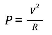
(Ohm’s law)
If the voltage doubles ( V2 = 2 V) we have:
We divide the two relationships by parts, simplify, solve for P2 and finally we have:

Since V2 = 2V (because we doubled the voltage) the previous relationship becomes:
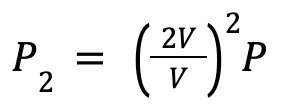
where 2V / V = 2 (if V ≠ 0) and 22 = 4
This means that the power of the transmitter must be quadrupled in order to double the amplitude of the signal (voltage) at the input of the receiver.
In high frequency HF (shortwave) radio communications, the International Amateur Radio Union IARU Region 1 has defined S9 as a receiver input power of -73 dBm, equivalent to 50 microvolts (μV) in a 50 Ω system. For the VHF bands the recommendation defines S9 as receiver input power of -93 dBm. This is equivalent to 5 microvolts at 50 Ω. Signals stronger than S9 are reported with an additional dB rating, such as “S9 + 20 dB“, indicating a signal 20 dB above the S9 reference level.
S Unit Corresponding Values
The table below shows the relationship of S units to the power and voltage of the received signal in a 50 ohm system on shortwave (HF):
| S Unit | Power (dBm) | Voltage (µV RMS, 50Ω) | dB above 1µV |
| S9 +10 dB | -63 dBm | 160 µV | 44 dB |
| S9 | -73 dBm | 50 µV | 34 dB |
| S8 | -79 dBm | 25 µV | 28 dB |
| S7 | -85 dBm | 12,6 µV | 22 dB |
| S6 | -91 dBm | 6,3 µV | 16 dB |
| S5 | -97 dBm | 3,2 µV | 10 dB |
| S4 | -103 dBm | 1,6 µV | 4 dB |
| S3 | -109 dBm | 0,8 µV | -2 dB |
| S2 | -115 dBm | 0,4 µV | -8 dB |
| S1 | -121 dBm | 0,2 µV | -14 dB |
Most analog S meters are not perfectly calibrated and are used as a relative means of measuring signal strength. However, Software Defined Radios (SDRs) provide extremely accurate measurements because they directly measure the amplitude of the signal.
Understanding S units and their relationship to the decibel helps radio amateurs to consistently evaluate signal strength and compare reception conditions between different receivers.
dBi and dBd
Let’s now say a few words about the dBi and dBd units of measurement that are used to measure antenna Gain.
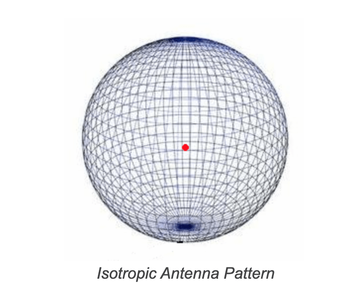
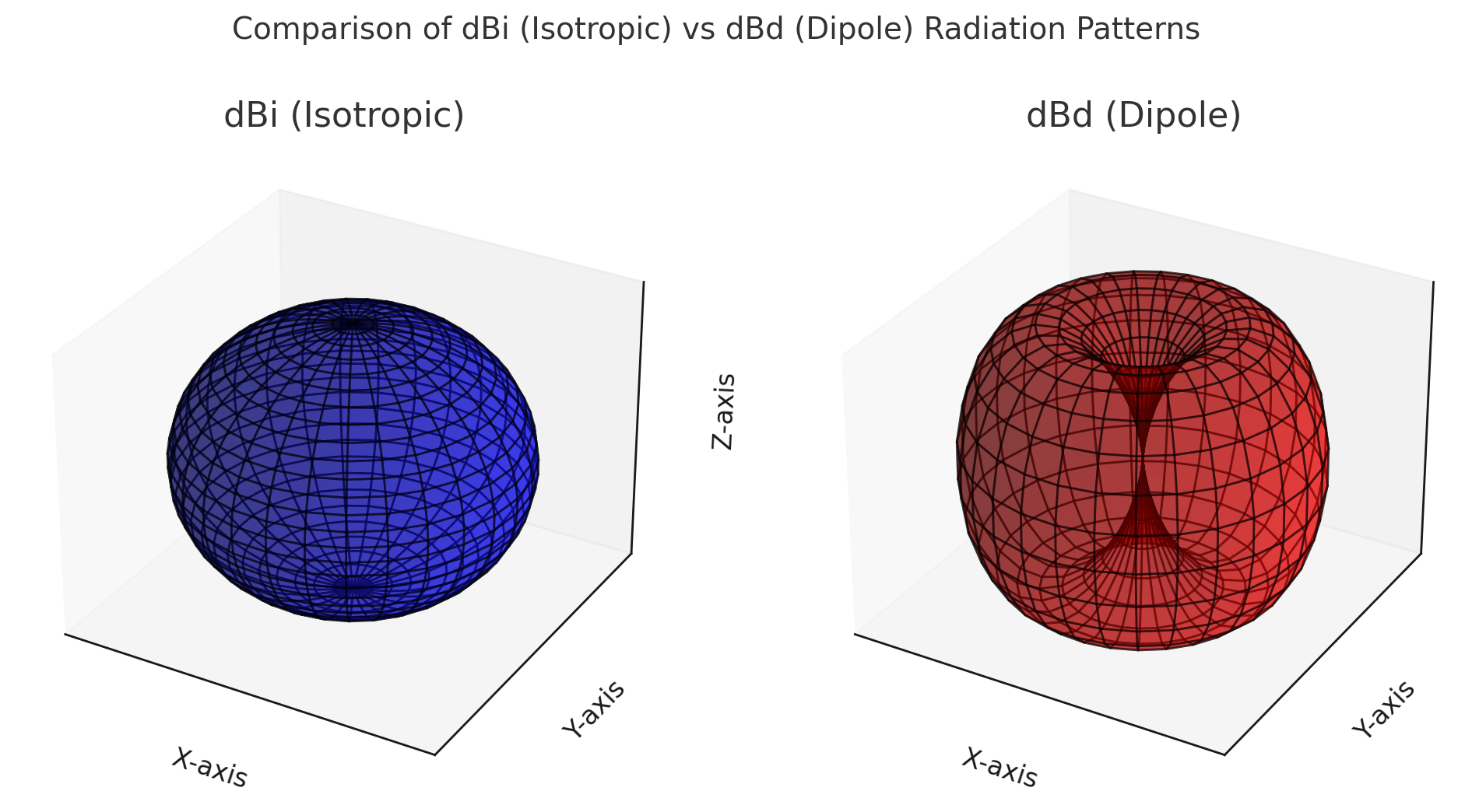
The dBi compares the gain of an antenna with that of an isotropic antenna (a theoretical, point source antenna that transmits uniformly in all directions).
The dBd compares the gain of an antenna with that of a halfwave (λ/2) reference dipole antenna in the same band as the antenna under comparison. The reference dipole antenna offers a fixed gain of 2.15 dBi.
The comparison towards the dBd is made as follows: Let’s say we transmit on some band with a halfwave (λ/2) dipole and a power of e.g. 100W, and, our correspondent receives our signal at S9 (S units).
If we transmit on the same band with another antenna, however only with 10W power this time and if this second antenna manages to produce the same signal level at the receiving end (with 10W instead of 100W), then we can say that this antenna has 10 dB Gain compared to the halfwave (λ/2) dipole, because it is as if it has effectively produced a tenfold increase in power (+10dB = 10x power increase).
Any antenna, of course, as a passive element actually has no gain. What we measure as gain is not some intrinsic power gain, but the ability of the antenna to direct all the transmitted energy in specific directions more efficiently.
If we want to express dBi in dBd, or, dBd in dBi we will have:
Gain in dBd = gain in dBi – 2.15 dB
Gain in dBi = gain in dBd + 2.15 dB
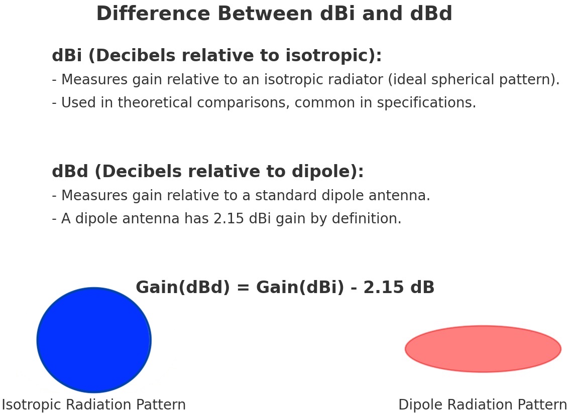
We can see that if we express the gain of an antenna in dBi it will appear to be 2.15 dB better than if we express it in dBd.
However, this is just a misconception, since as you can see above, a 10 dBd antenna has exactly the same gain as a 12.15 dBi antenna.
Antenna System Gain
When we refer to an antenna system, we mean the sum of all the components that make up the system. This includes the antenna itself, the transmission line (ie coax, ladderline etc.), and any other element that is inserted between the transmitter’s output and the antenna’s input, such as tuners, filters, connectors, etc.
In calculating the total Gain of an antenna system, it is important to remember that this is the difference between the Gain of the antenna and the total attenuation caused by the transmission line and the remaining interconnecting components.
For example, if an antenna has a Gain of 9 dBd (or 11.15 dBi) and the total attenuation from the transmission line, tuner, low-pass filters and connectors is -3 dB, then the resulting Gain of the antenna system will be:
9dBd (or 11,15 dBi) − 3dB = 6dBd (or 8,15 dBi)
Hence, when designing an antenna system, it is important to take into account not only the nominal gain of the antenna, but also the losses introduced by the intermediary components.
Calculating the Total Gain in a Multi-Antenna Array
We should remember that increasing Gain by doubling the number of antennas is a fundamental principle in antenna system design. The rule of +3dB per doubling of the radiation system is derived from the physics of signal combining (constructive interference) and power distribution.
Some points worth noting when combining antennas in an array are:
- The distance between them. The distance between the elements of the array affects the angular distribution of the radiation lobes.
- The relative phase of the signals. If the antennas are not synchronized in phase, cancellation lobes can occur, which reduce the efficiency of the array (destructive interference).
- In phased antenna arrays, the change of relative phase between the array elements allows dynamic control of the beam direction without requiring mechanical movement of the antenna (beam forming & steering).
- The polarity of the antennas. Different antenna polarities of the system can affect the polarization of the transmitted signal.
In practice, due to non-ideal conditions, the increase in Gain may be slightly less than the theoretical value due to coupling losses or imperfections in the power distribution system.
Examples
If we have an antenna with a Gain of 6 dBd (or 8.15 dBi) and add a second antenna of the same type, then the total Gain of the system will increase by 3 dB, reaching 9 dBd (or 11.15 dBi).
To increase the system gain to 12 dBd (or 14.15 dBi), we need to double the radiating system again, i.e. add two more antennas, creating a four-antenna system.
If we wish to increase the Gain by another 3 dB, reaching 15 dBd (or 17.15 dBi), we will need to double the radiation system again, adding four more antennas, for a total of eight identical antennas. This process can be repeated in the same way indefinitely.
Every 3 dB increase in the Gain of an antenna system requires doubling the number of existing antennas.
Epilogue
In concluding this article, I would like to say that I have not avoided some basic mathematical relationships and expressions based on Ohm’s law and the properties of decimal logarithms, because I considered their use necessary, as their omission would lead to an incomplete substantiation of the article.
I hope that you will find this approach to decibels useful, making it both easier for you to make measurements and to understand the conversions between units in telecommunications.