I wanted a quick & easy to install high-power multiband wire antenna for field-day and temporary operations and I’ve been hearing a lot about End-Fed Halfwave antennas lately.
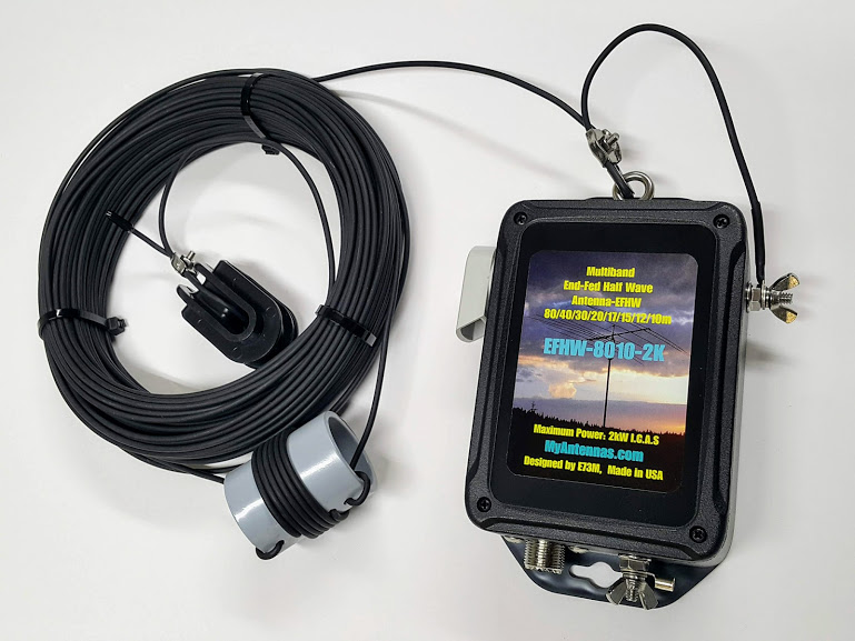
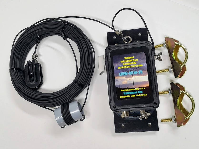
So I recently purchased the EFHW-8010-2K from Myantennas.com which is a company that I’ve come to trust for their high-quality components, workmanship and excellent CMC products (more on those in a future post).
The EFHW-8010-2K is the heavy-duty QRO version which supports up to 2kW ICAS power levels. It is 39.6m long and is resonant on 80 through 10 meters, while the construction really is top-notch. Perfect for the abuse I’d put it through if need be (EMCOMM, DXpeditions, Contesting etc).
However, after reading through all the End-Fed “hype” I became curious and wanted to see how this antenna actually performs. Well, at least theoretically through software simulation. I wanted to see what differences it has, if any, to a random wire, to an Off-Center Fed Dipole (OCFD / Windom) and to a classic dipole antenna. So I fired up MMANA-GAL, and looked in the antenna library for a ready modelled EFHW file, albeit, there wasn’t one!…well there wasn’t one like mine that is.
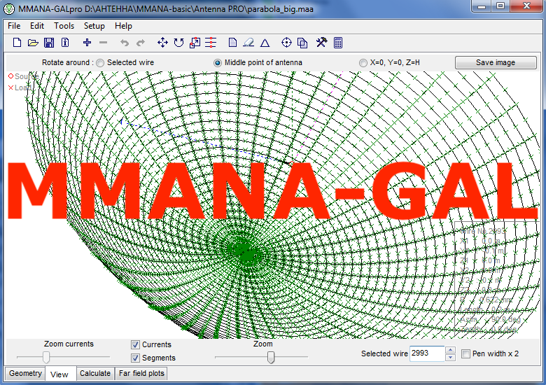
MMANA-GAL is a popular antenna design, analyzing and modelling software tool, that is relatively easy to learn and use. It is arguably simpler, and in some cases more powerful, than other antenna modelling software such as EZNEC or 4nec2, and that is why it has become popular for relatively simple antenna modelling. It comes in two versions, the basic version which is free, and the PRO version which is paid. You can download MMANA-GAL Basic from here: http://gal-ana.de/basicmm/en/#18
After searching online, I couldn’t find a single reliable model of an EFHW in MMANA. There were several variants, however, none were accurate to my antenna’s specifications. So I decided to design and build my own model from scratch, which is a pretty simple thing to do in MMANA-GAL.
I decided to design and build my own model from scratch, which is a pretty simple thing to do in MMANA-GAL
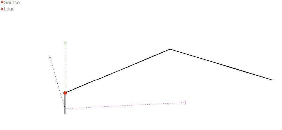
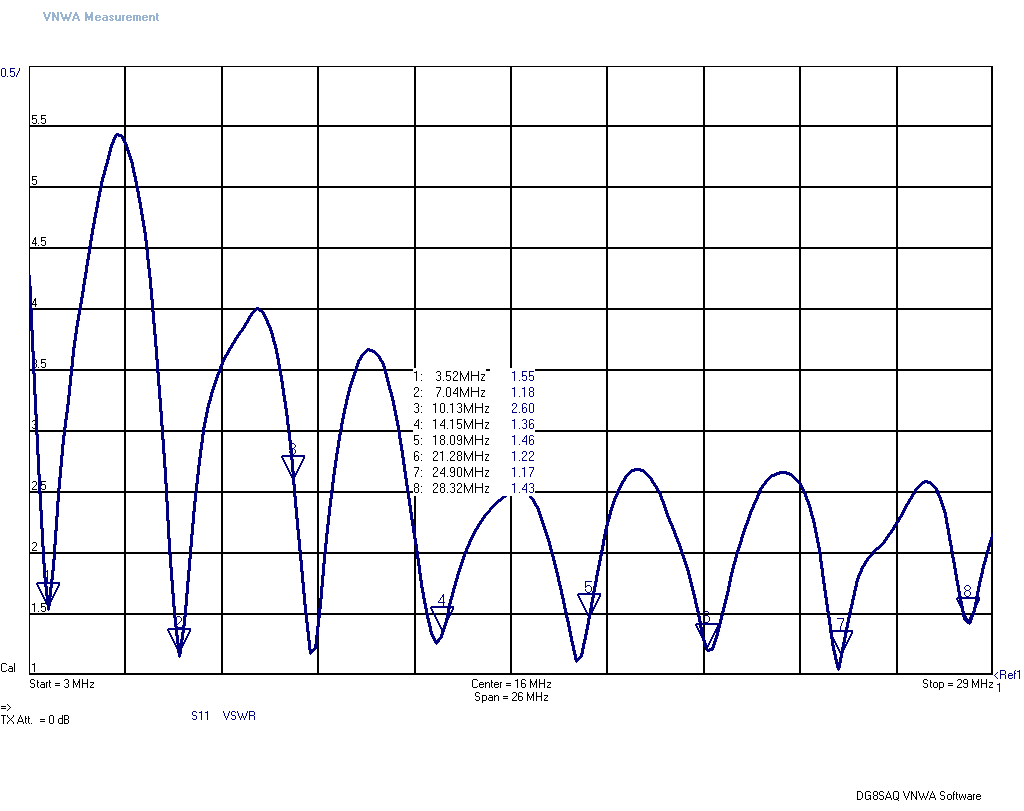
My EFHW is cut for 80 meters, and the manufacturer states that it has low VSWR on every amateur band, all the way up to 10M. Using MMANA-GAL I modelled it in an inverted-V topology since this would likely be the most common topology one would use, and it’s very simple to change it (ie to a sloper, horizontal wire etc).
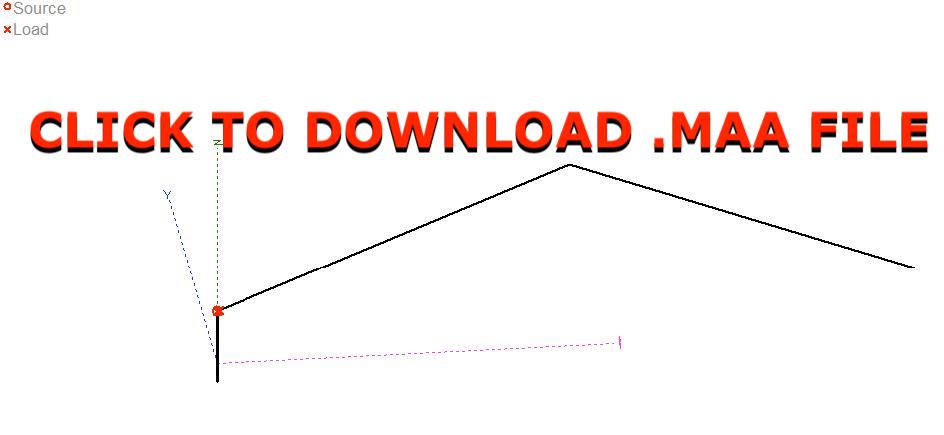
You can download the MMANA “.maa” model file that I created for the EndFed Halfwave 80Μ-10M Antenna (EFHW-8010.maa) by clicking on the image or click here to download.
Feel free to use the antenna model file and customize it to your specific needs in MMANA-GAL. It’s very interesting to simulate this antenna’s performance and radiation pattern in various topologies & installation setups, and to compare it to other similar antennas.
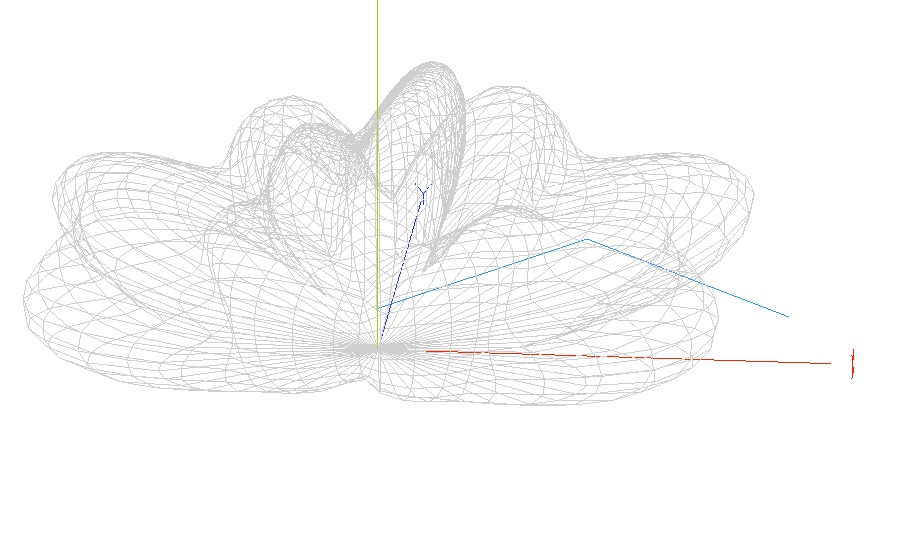
Additionally, below are some screenshots of the far-field plots and antenna layout from my model (click to enlarge):
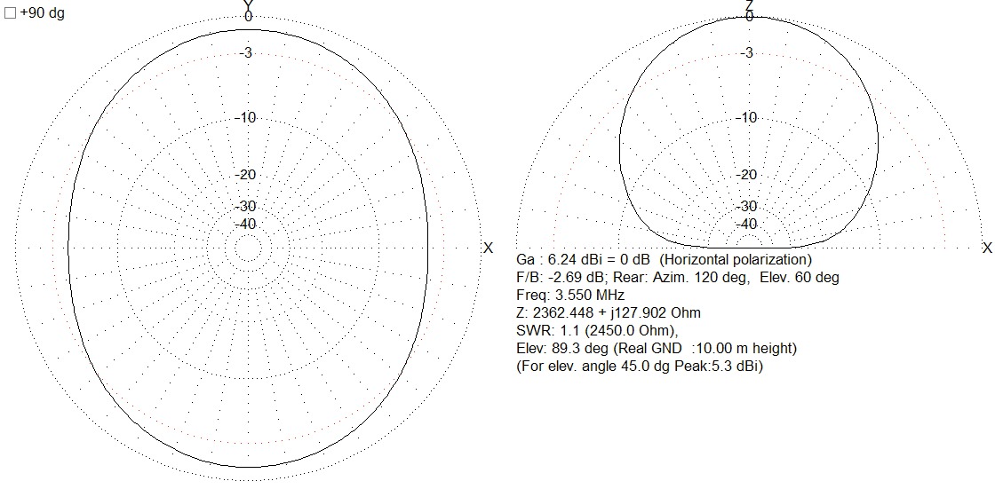
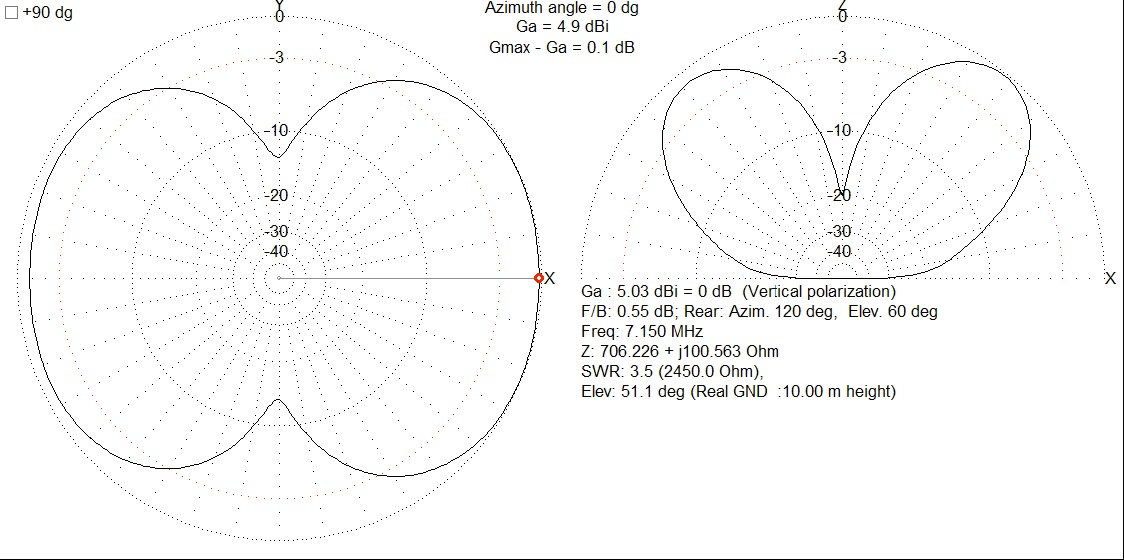
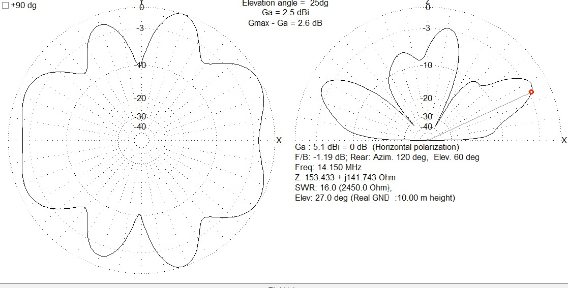
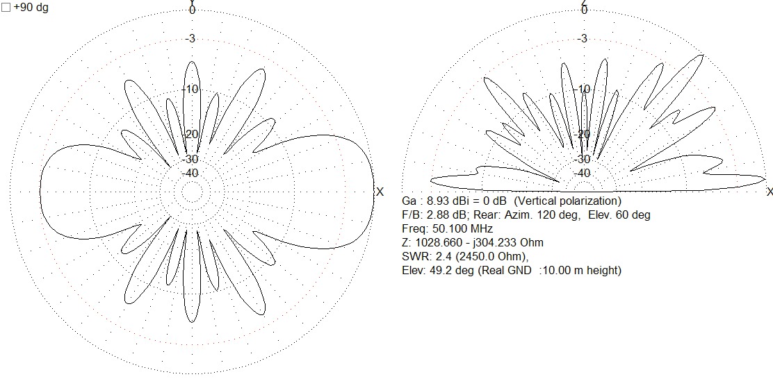
The radiation pattern is very similar to a standard dipole on its fundamental (ie. the first resonant frequency band), and equally very similar to an Off-Center-Fed-Dipole on the resonant harmonic bands. I read somewhere that essentially there is no such thing as an EFHW, and that it actually is an extremely off-center fed dipole. Well, I can confirm this by looking at the radiation pattern, and its electrical characteristics. Regardless of how you want to call it, it is essentially a dipole fed from one wire end with an impedance transformer to match the feed-point impedance to the transmission line impedance, that’s about it!.
Generally speaking EFHW antennas seem to be a good compromise antenna due to their increased practicality of feeding at the wire-end, which is their significant advantage. However expect performance similar to (or slightly worse than) an OCFD/Windom, nothing more.
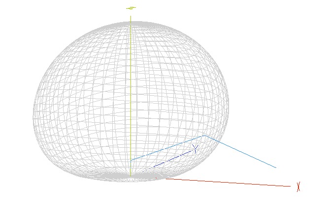
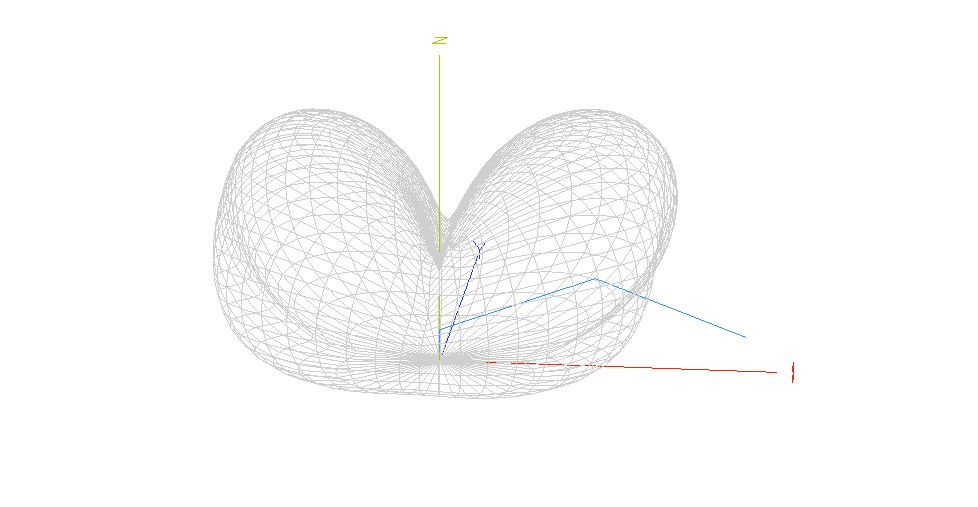
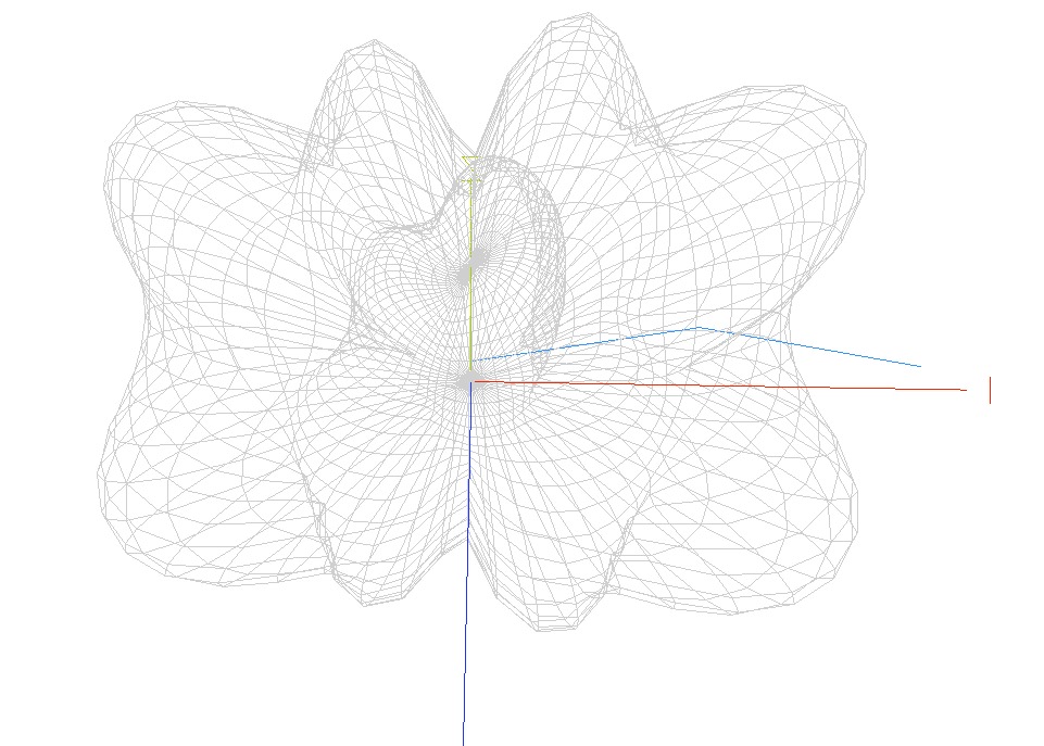
An interesting thing you might notice when looking at the 3D radiation pattern on the base frequency, is that only about 1/4λ of the wire closest to the feed point is doing most of the radiating, with the peak current occurring around the center. While the far side (remaining 1/4λ) is not doing much at all. On harmonics, this whole phenomenon re-occurs every 1/4λ of the harmonic frequency until about the center.
You also might need to be a bit careful with the hardware used at the feed-point when operating under high power QRO. There is a serious risk of arcing and voltage breakdown, due to the very high-voltage developed.
This is due to the wire end impedance of a 1/2λ dipole being close to 2450Ω, which is the feed point impedance of an EFHW (ie at the secondary of the impedance matching transformer).
So by using OHM’s law V = √(P x R), if we feed the antenna with 1kW RF out and with the EFHW feed point impedance of 2.45kΩ, then we will see 1.57kV developed at the feed point (ouch!).
The 8010 from Μyantennas is rated at 2kW ICAS so it shouldn’ t be a problem with 500W+ CW, but still, it’s scary when you think about it 🤯
Generally speaking, EFHW antennas seem to be a good compromise antenna due to their increased practicality of feeding at the wire-end, which is their significant advantage. However expect performance similar to (or slightly worse than) an OCFD/Windom, nothing more. There is no pot of gold at the end of this rainbow! 😀
73’s to all! de Andy SV1DKD