An Introduction
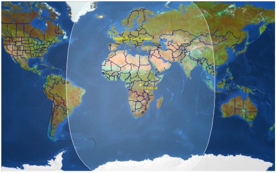
Qatar OSCAR 100 launched on November 15, 2018, and is the first geostationary satellite with an amateur radio transponder on-board. It is a joint project of the Qatar Satellite Company (Es’hailSat), the Qatar Amateur Radio Society (QARS) and AMSAT Deutschland (AMSAT-DL). Set on a geostatic orbit at 25.9 ° East, its main service is to broadcast television to the Middle East. What makes it interesting for us is that it also has two amateur radio transponders. While simultaneously, because of its location, it covers an area from Brazil to Thailand!

QO-100 Frequencies
Oscar 100 transmits (with both transponders) on 10.4GHz (so we receive it here – ie the downlink freq), while it receives on 2.4GHz (so we transmit here – ie the uplink freq). The problem is we need a radio for these frequencies!
QO-100 BandPlan
As mentioned above, QO-100 has two transponders: a Narrowband (NB) and a WideBand (WB) transponder.
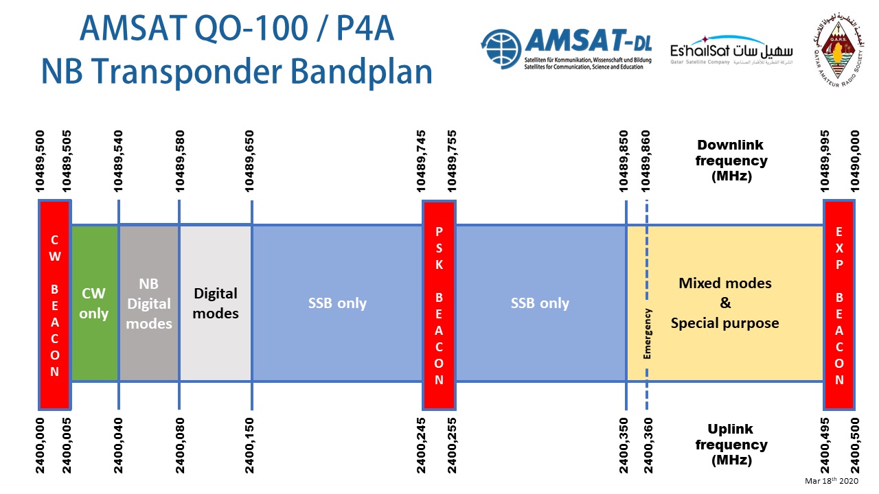
ΝarrowΒand
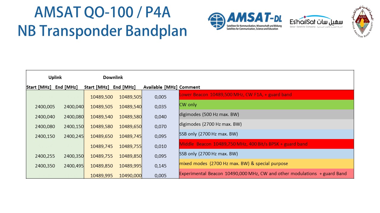
The NarrowBand “NB” transponder is intended for conventional, analog and narrowband digital signals, with a maximum bandwidth of 2.7 kHz. FM (analog or digital), DSTAR, and C4FM modulation is not allowed. Broadcasts should not be made beyond the two boundaries of the transponder bandwidth, and in particular, broadcasts below the lower beacon or above the upper beacon shall not be permitted. Also, our transmitted signal may not be larger than the beacon signal.
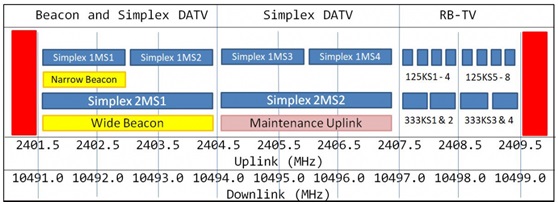
WideBand
The WideBand “WB” transponder is for DATV (DigitalAmateur TeleVision). The signal must be transmitted via DVB-S2 (Digital Video Broadcasting-Satellite-Second Generation). As a general principle, the transponder should only be used for short tests and contacts. It is also true here that our transmitted signal must not be greater than the beacon signal.
What will we need?
To see what we need, let’s start from the beginning. Our goal in this article is to help you understand what is needed to use the “NB” Narrowband transponder.
The modes used on the NB transponder are:
- SSB
- FreeDV
- CW
- RTTY
- SSTV / KG-STV
- FAX
- Fieldhell
- Digimodes like PSK31, FT8 etc.
Reception (RX)
As mentioned above, the SSB, CW, SSTV, or PSK signals from Oscar 100 are received on the 10.4 GHz band. To solve the problem of lack of a radio for these frequencies, we need to use the appropriate LNB to convert the 10.4 GHz band, typically to 739 MHz, where we can receive with the help of an SDR receiver.
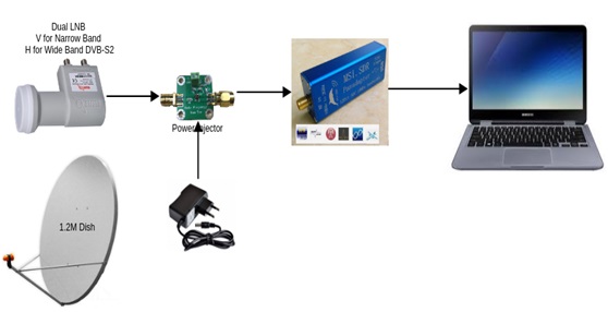
The ground station for receiving Oscar 100 in its simplest form consists of the following components:
- High gain parabolic dish as a receive antenna
- LNB (low noise block) with a PLL and a 25MHz external oscillator reference, or, a GPS clock reference
- BIAS-T to power the LNB
- SDR receiver (RTL) 0,5ppm, or, a downcorverter
- RG6U 75ohm Sat-TV grade coaxial cable
- PC with SDR console version 3+ software installed
- 12v or 18v Power Supply
- SMA adaptors and coaxial pigtails
Receive Antenna – Satellite Dish
You can use common off-the-shelf satellite dishes with a diameter of 80cm to 120cm. E.g. https://www.e-shop.gr/engel-axil-doryforiko-katoptro-lh-105m-p-PER.705170
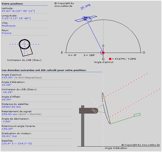
Dish aiming and alignment can be accomplished using the following coordinates, using a near-by to our coordinates sattelite (25.9° East). For instructions see https://satlex.de/en/azel_calc-params.html?satlo=&user_satlo=25.9&user_satlo_dir=E.
LNB
We can use a standard common LNB, or, preferably one that has a GPSDO input (external GPS controlled oscillator reference) so that frequency stability is maximised and the receiver doesn’t “drift”. Alternatively, you can find simple and economical LNBs online, which can become very stable with a PLL modification.
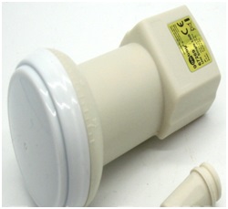
LNB 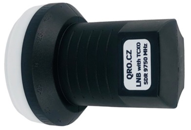
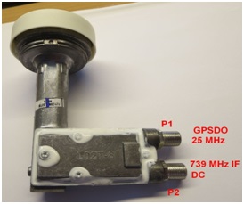
The receive frequency of an LNB is commonly 9750MHz (via SDR software it can be shifted to 10.4GHz), and it usually down-converts this to 739MHz.
LNBs have two antennas, one vertical and one horizontal. For the NB transponder, we need to power the LNB with 12V, so that we can activate vertical polarization. If we want to use the WB transponder we need to power the LNB with 18V, so we can activate horizontal polarization.
I recommend purchasing an LNB that can be modified for frequency stability, or buying one that has already been converted.
or a purchase a ready solution from https://remoteqth.com/lnb.php
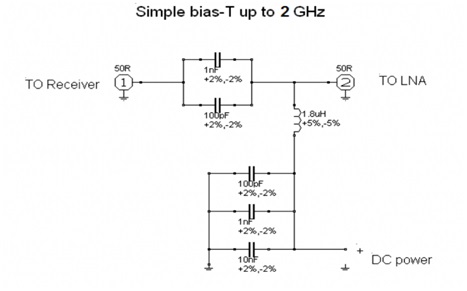
Bias-T
The LNB supply voltage is, as mentioned above, 12V for the NarrowBand transponder and 18V for the wideband transponder.
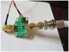
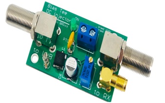
The Bias-T circuit can either be purchased ready-made or manufactured according to the following design (right).
In the circuit diagram (right), you’ll find a blocking capacitor between the LNB and our receiver. This is needed in order to block the DC voltage which is applied to the LNB, via the inductor (which blocks RF from going to the supply). These are needed if you’re going to build the circuit on your own.
Alternatively, ready-made solutions can be purchased either from https://remoteqth.com/lnb.php
SDR
For a receiver use an SDR (software defined radio) which can receive up to 1GHz and with a 0.5-1ppm TXCO so that it doesn’t “drift”.
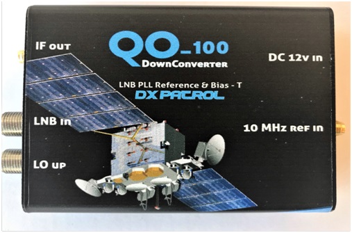
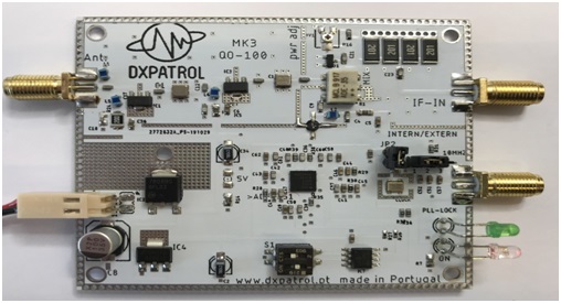
DownConverter
Alternatively, instead of an SDR as a receiver, you can use a Down Converter, such as the one available from DX PATROL, which has an LNB input and an output on 28, 144, 432 or 1296 MHz. This allows you to receive OSCAR-100 directly on your HF, or, VHF/UHF all mode transceiver. See https://www.dxpatrol.pt/index.php/kits
SDR Software
As previously mentioned, you’ll also need to use software on your computer in order to operate the SDR. For example https://www.sdr-radio.com/
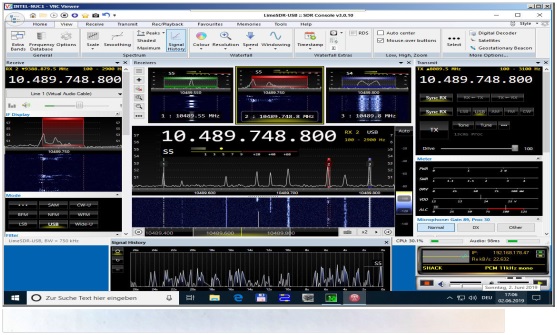
Instructions for configuring the software can be found here: https://www.f5uii.net/en/reception-satellite-qatar-oscar-100-phase-4a-eshail-2-sdr-console-sdr-radio-software/
Coaxial Cable
To connect the LNB to the BIAS-T, you will need a 75 ohm tv-sat cable. E.g. https://www.stavrianos-dw.gr/m.index.php?cPath=327_688_364
Transmission (TX)
Signal transmission to QO-100 is done on the 2.4GHz band, and you’ll need:
- V-U all mode transceiver, or, a conventional HF rig
- Transverter, or, just an Up Converter
- Low-Loss Coaxial Cable such as ULTRAFLEX-10 or similar
- Transmitting antenna for 2.4GHz
- 80cm-120cm diameter Satellite Dish
- Optionally an amplifier for 2.4GHz
Transceiver
Depending on the type of transceiver you are going to use (HF or all-mode VHF/UHF rig) you’ll also need to select the corresponding transverter, or upconverter.
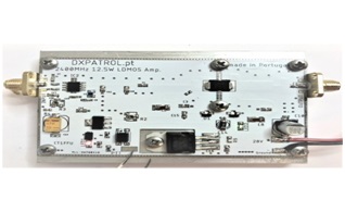
Transverter or Upconverter
A good solution is the Transverter from sg-lab with an input frequency of 430MHz (ie it needs a UHF All-Mode rig) and an output frequency of 2.4GHz, with 2 Watts of power. Its advantage is that, in addition to transmission, it can also be used for reception at 2.3-2.425GHz (in our case, of course, we only need it to transmit). Additionally, with this solution, we also won’t need to purchase an amplifier. See http://www.sg-lab.com/TR2300/tr2300.html

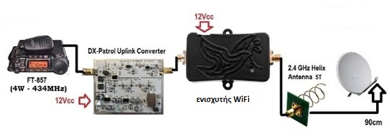
A second solution is the Up Converter from DXPATROL, which accepts input frequencies of 28, 144, 432 or 1296 MHz (ie any common HF rig will do) and it transmits on 2.4GHz. Note that it only can transmit (no reception capability), and its power output is only 250mW. This means that you will probably need an amplifier, or, a higher-gain antenna (ie large 1.5m dish) in order for your signal to make it to the satellite. https://www.dxpatrol.pt/index.php/kits
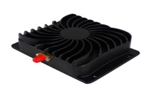
Power Amplifier
We can use common WiFi amplifiers. But there are also more noteworthy amplifiers designed specifically for this particular use. For example see:
https://www.passion-radio.com/satellite-qo-100/ep-ab003-797.html
Transmit Antenna
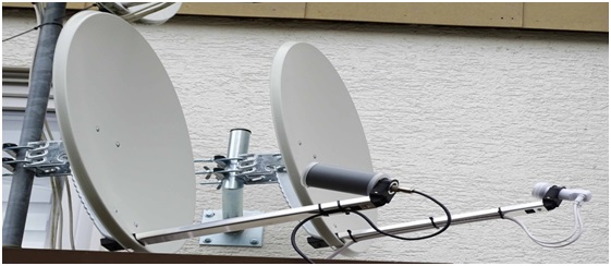
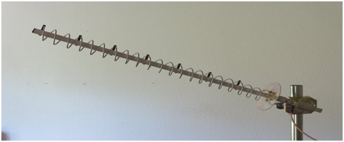
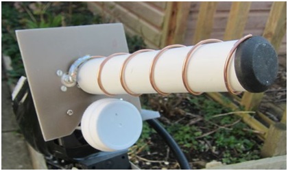
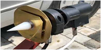
The appropriate transmission antenna for QSCAR-100 is the so-called “RHCP” (right-hand circular polarization) antenna. Such are the POTY and Helix antennas shown in the pictures. Both of these antennas are easy to homebrew and manufacture. See http://www.hybridpretender.nl/patch.pdf and http://f5ad.free.fr/Liens_coupes_ANT/G/PA3FYM%20Helice%202300.htm
These antennas (in the example images), are tuned to be resonant on the 2.4GHz band. They are mounted on the satellite dish, along with the LNB, at the dishes corresponding focal point. They transmit pointing into the parabolic dish from this point, which then reflects and focuses the transmitted signal onto the satellite.
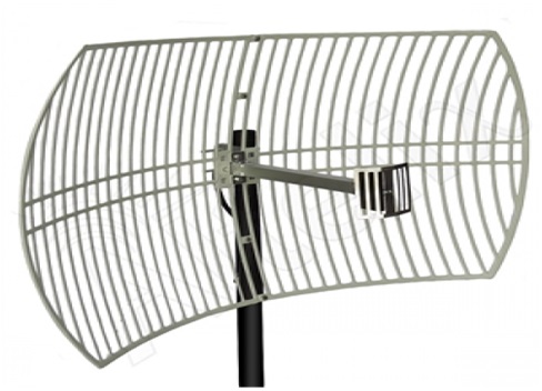
We don’t need to use a satellite dish at all if desired. Instead, we can use a multi-turn HELIX type antenna, or, WiFi Parabolic grid type antennas (Caution: they are not “RHCP” polarized, and thus should be used as a last resort, ie. only if we already have one). The best option is to use small-sized antennas in combination with a parabolic dish as described above.


Note that the transvertor or the upconverter (whichever is used), as well as the amplifier (if used) need to be placed as close to the transmit antenna as possible. Don’t forget that coax cable losses on 2.4GHz are significant. You can also simultaneously use the same satellite dish both for reception and transmission, just by mounting the LNB and the TX antenna together.
Coaxial cable for transmitting
Use coax designed for WiFi frequencies which has low loss at 2.4GHz, for example, Ultraflex-10 is a good choice: https://www.freebytes.com/catalog/product_info.php?products_id=1813
Below, in the corresponding video, you can see an example of TX and RX via QO-100
Useful links
- https://www.qsl.net/sv2hzt/OSCAR%20100%209-12-2019.pdf?fbclid=IwAR2wyb-Gcy5Pw180h91WNPf_1sJ24XJA6QiavrmZtSV7rx2VbuSQNnVVmec
- https://forum.amsat-dl.org/index.php?board/3-qo-100-es-hail-2-p4-a/
Equipment Suppliers
- https://www.sv1afn.com/en/products/
- http://www.sg-lab.com/TR2300/tr2300.html
- https://www.dxpatrol.pt/index.php/kits
- https://remoteqth.com/lnb.php
- https://shop.kuhne-electronic.com/kuhne/en/onlineshop/Hailsat/
- https://www.ebay.ie/itm/NESDR-SMArt-SDR-Premium-RTL-SDR-USB-Stick-w-0-5PPM-TCXO-SMA-R820T2-RTL2832U/152704226308?hash=item238de19404:g:I20AAOSwzJ5XbKyz
To SZ1A and all of you, I wish you good luck and many contacts.
George Sofronas, SV1ELF
Electrical Engineer